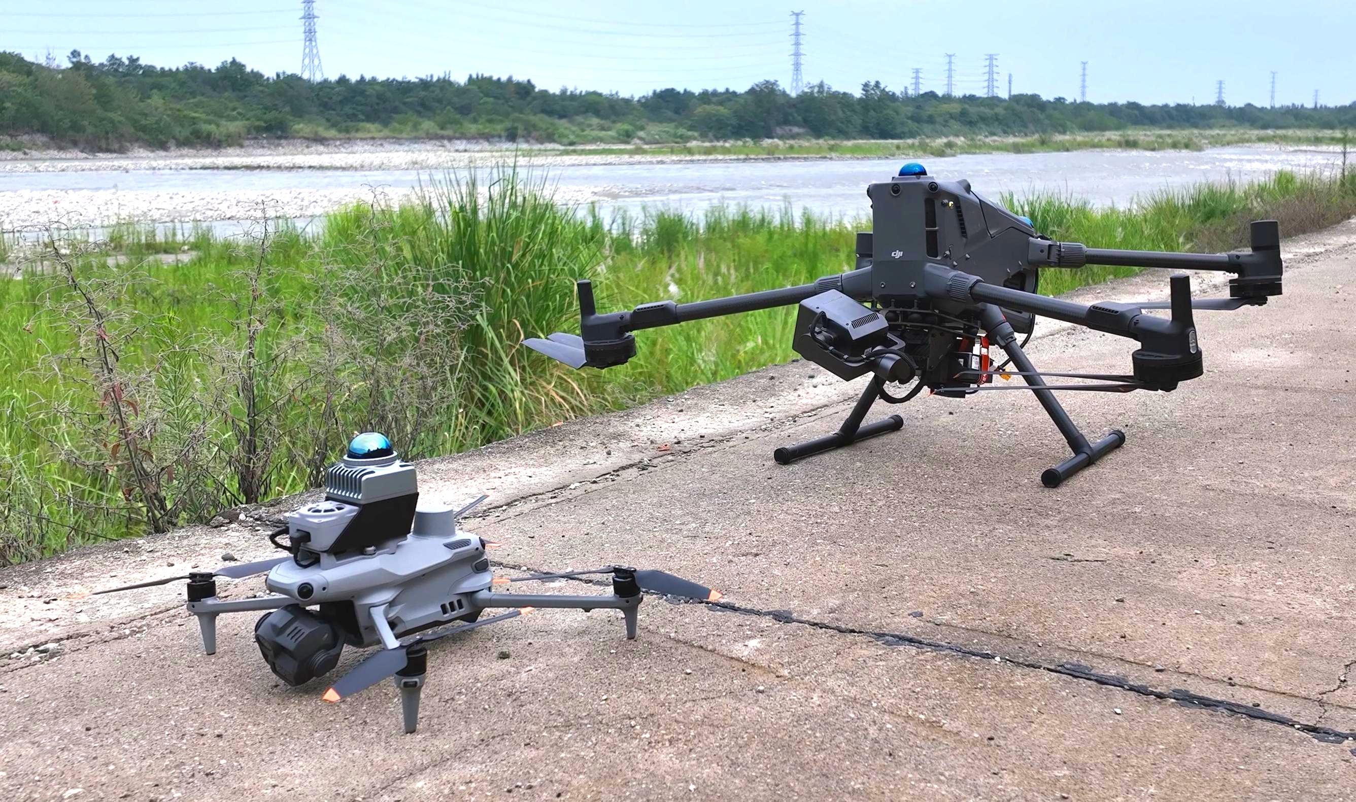
Bridge undersides are challenging to inspect: satellite signals are obstructed, while piers, pier caps, bearings and girders overlap. Every component needs clear photographic coverage.
Teams often use a large aircraft such as M400 for under-bridge inspection because its endurance and payload suit large areas. Detailed bearing photography and some complex spaces, however, call for complementary aircraft and routes.
AIFORAIL combines M400 and M4 so that each aircraft follows routes suited to its strengths. This article covers bearings, modeling and complex environments, then explains the workflow from flight and acquisition to analysis.
01 Why bearings are difficult to photograph: angles and clearances
Bridge bearings sit close to the underside. A near-horizontal view helps avoid obstruction by the pier cap, making aircraft clearance and camera mounting position important.
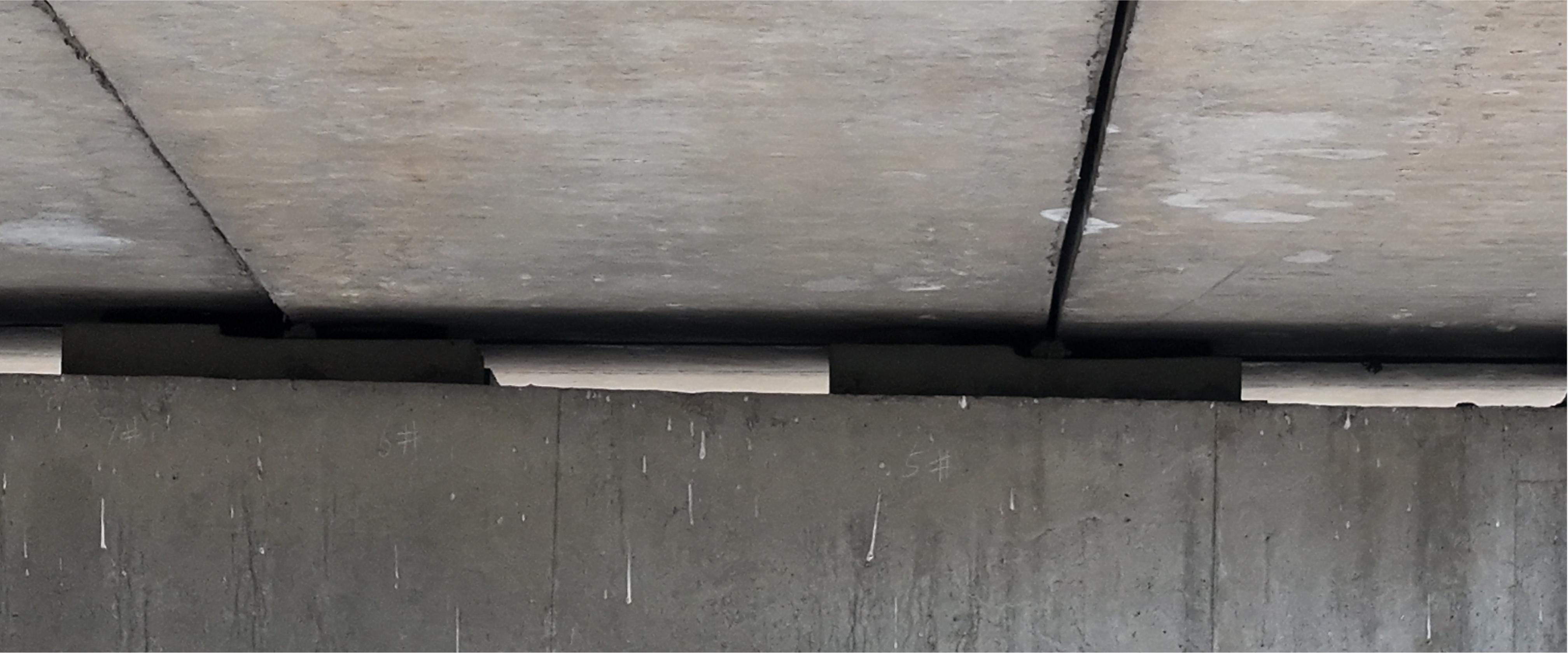
In the M400 configuration discussed here, overhead clearance is at least 2 m, with routes generally planned at 3 m or more to account for positioning error and other factors. Its underslung gimbal, without a top-mounted camera, combines a lower viewpoint with greater overhead clearance, making near-horizontal bearing views difficult.
Moving 20–30 m away can make the view more horizontal, but also makes bearing detail harder to resolve. Viewing angle and detail resolution must be considered together.
Raising the camera or reducing clearance requires caution
One approach is to modify M400 with a top-mounted gimbal bracket. Raising the camera by about 30–50 cm offers limited angle improvement relative to the 3 m overhead clearance used in this configuration.
Another approach is to disable collision protection and reduce overhead clearance to about 1 m, but that weakens the existing safeguards. Cables and ropes may be present, and direct observation from beneath the bridge may be impossible. Flight and equipment risks should not be overlooked for the sake of a camera angle.
M4 handles detailed bearing photography
The M4 setup described here uses about 1 m of overhead clearance and a high-magnification zoom lens to photograph bearing details from 15–20 m away. Dedicated M4 bearing routes provide viewpoints that are difficult for a larger aircraft to obtain.
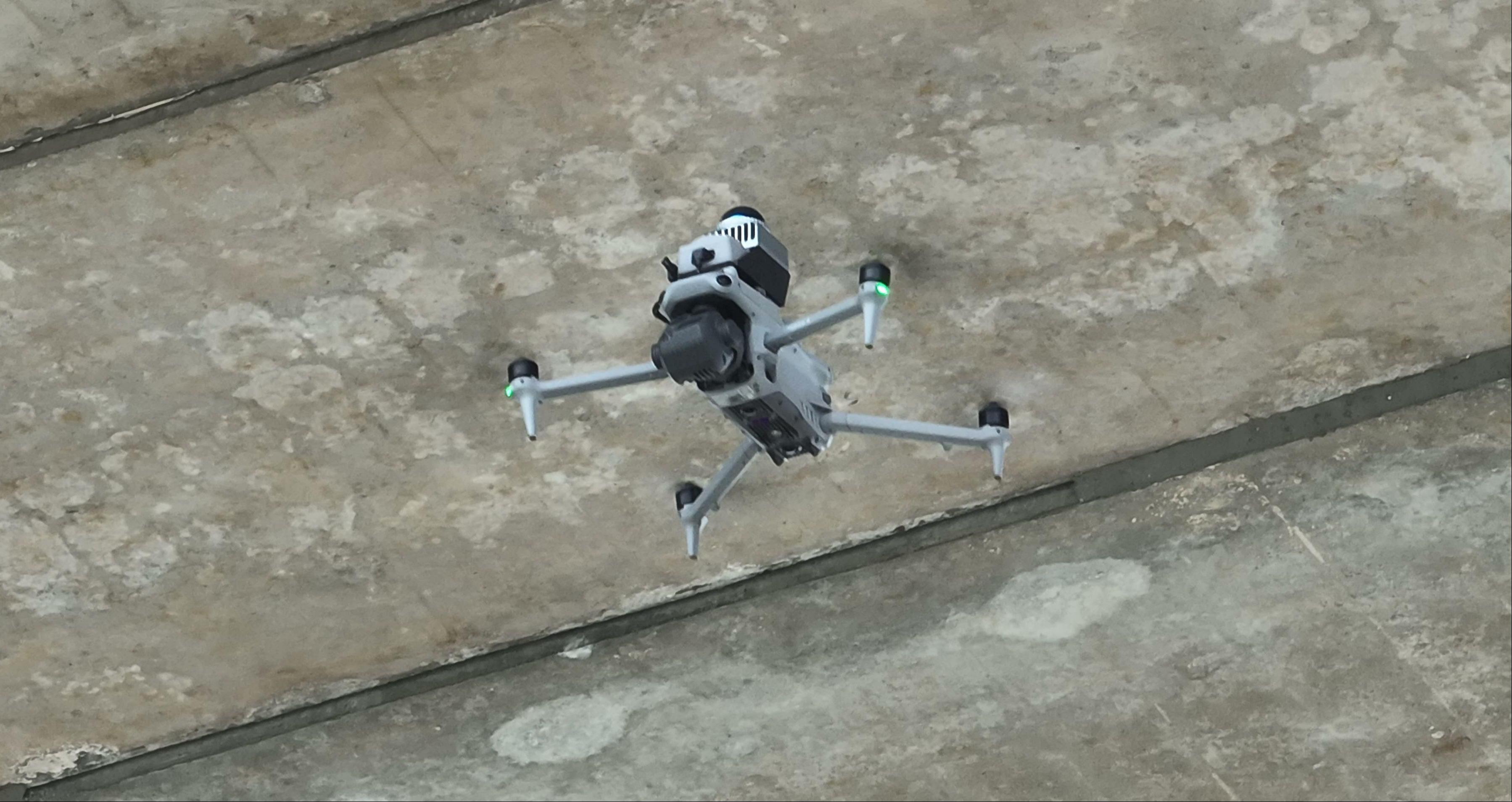
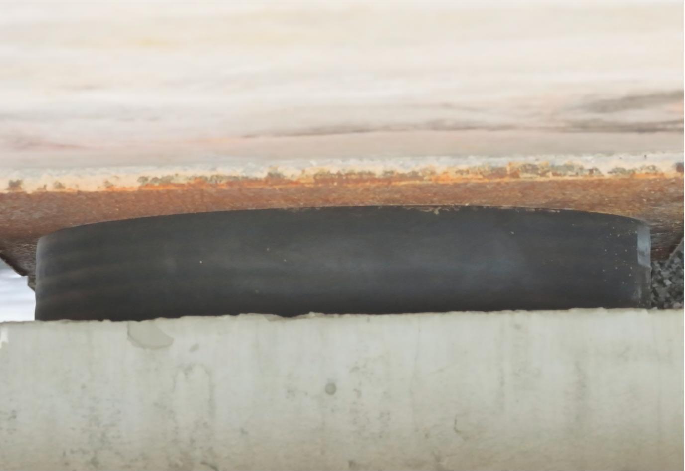
These distances describe the configuration in this article, not universal safe values for all aircraft, payloads or sites. Actual operation must account for equipment requirements, obstacles, positioning status and site-specific risk assessment.
02 Modeling and defect mapping: M4 supports 3D bridge acquisition
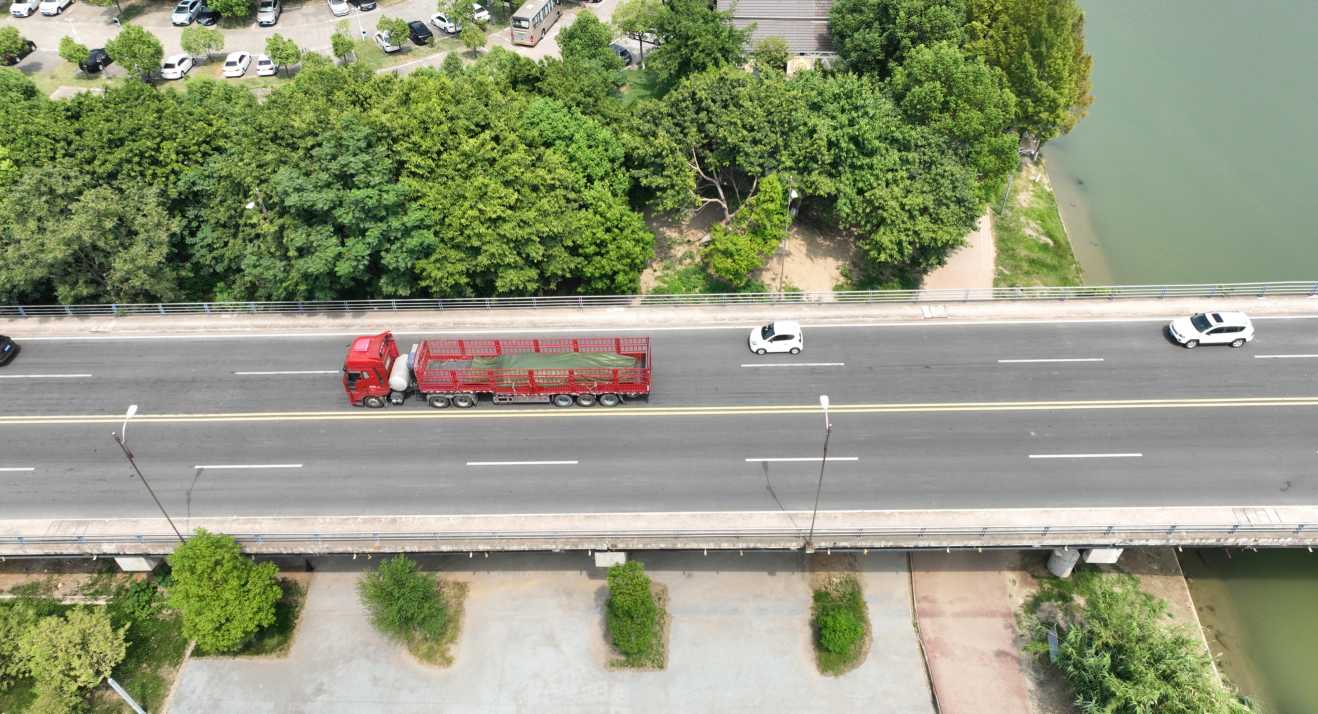
Route planning and defect mapping require a 3D bridge model. M4 can capture oblique imagery above and below the bridge, with modeling completed using software such as DJI FlightHub or DJI Terra.
M4 is compact and maneuverable, supporting image acquisition above and beside the bridge. Where trees, buildings or terrain restrict access, capture positions can be selected within available space to supplement model coverage.
03 Complex environments: smaller aircraft complement restricted-space work
Low clearance, dense cables, trees or buildings may prevent M400 from entering or operating. Depending on site conditions, M4 can inspect some of these complex areas and collect defect imagery. Aircraft selection remains subject to a safety assessment.
04 AIFORAIL collaboration: from flight and capture to analysis
Detailed under-bridge inspection benefits from complementary aircraft with clear responsibilities. AIFORAIL supports M400 and M4 with positioning and navigation, route planning, and defect processing.
Positioning, navigation and traceability: INES + AGS
INES can be mounted on M400 and M4. Together with the AGS controller ground station, it transitions between RTK and LiDAR SLAM positioning in open areas and under bridges, supporting navigation, route execution and mission monitoring where satellite positioning is unavailable.
INES records the position and orientation of each photo and transforms them into the bridge model coordinate system. This enables photos and defects from either aircraft to be associated with the model and individual components for traceability and analysis.
Route planning: ARP supports both aircraft
ARP supports M400 and M4, generating component-based inspection routes matched to each aircraft's collision-protection clearances and camera, so tasks align with platform capabilities.
Defect processing and reports: bridge inspection platform
The bridge inspection platform accepts different image sizes and formats from M400 and M4. It combines AI defect detection, professional review, model and component association, and inspection report output in one platform.
05 Roles at a glance: aircraft and software responsibilities
| Role | Typical applications | Key capabilities |
|---|---|---|
| M400 | Large girder undersides, piers and bridge sides | Use endurance and payload capacity for large-area inspection. |
| M4 | Bearings, modeling capture and restricted-clearance areas | Combine a compact airframe, zoom imaging and tailored routes for detailed capture. |
| INES + AGS | Navigation and photo traceability without satellite positioning | Transition between RTK and LiDAR SLAM and record photo positions and orientations. |
| ARP + inspection platform | Route planning and defect analysis | Match aircraft parameters and connect AI detection, review, mapping and reporting. |
Closing thoughts
Detailed under-bridge inspection is not about assigning every task to one aircraft or sacrificing safety for a camera position. Recognizing platform limits and combining complementary capabilities is the starting point.
M400 covers large areas while M4 complements detailed and complex tasks. INES and AGS support positioning, execution and traceability; ARP and the bridge inspection platform connect mission preparation and results. Contact us to discuss an M400 + M4 configuration for your bridge project.