Centralized Onboard Computing
Processes sensing data and intelligent analysis locally on the train, reducing movement of raw data across the system chain.
 Contact Us ↗
Designed for onboard rail deployment, it connects front-end sensors and vehicle signals, performs local data processing, intelligent analysis and business coordination, and provides the computing foundation for driver information and system integration.
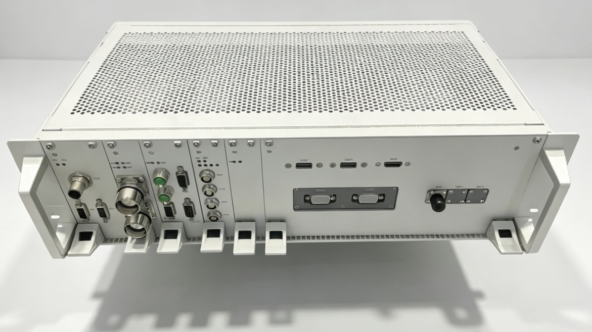
AFR540-T addresses multi-source data processing for TIDS with onboard processing, network communication, serial communication and hardwired I/O. Its modular front panel supports onboard-cabinet integration and clearly separates sensor access, commissioning, maintenance and vehicle coordination.
Processes sensing data and intelligent analysis locally on the train, reducing movement of raw data across the system chain.
Network, serial, hardwired and commissioning interfaces support sensor and vehicle-system connectivity.
A standard 19-inch 3U structure supports onboard deployment through front-panel connections and mechanical fastening.
Uses wide-range power input, with temperature, humidity, shock/vibration and EMC requirements defined in the datasheet.
The main computer is the data and business hub of TIDS. Connected devices, algorithm functions and vehicle interfaces are defined by the project solution.
Receives camera, LiDAR and other front-end device data over Gigabit Ethernet.
Organizes multi-source onboard data in a unified environment for fusion analysis.
Runs obstacle-detection and related application algorithms onboard.
Coordinates information with the DMI and vehicle systems through network, serial or hardwired interfaces.
Interface categories are based on the AFR540-T V1.0 datasheet. Final quantities, connector definitions and protocols are subject to the project interface-control document.
Supports DC 77–137.5 V input, with DC 110 V recommended. Uses a standard 19-inch 3U chassis, cabinet-mounted with four M6 front-panel fasteners.
The following content is based on the current V1.0 datasheet for preliminary planning. Formal selection, acceptance criteria and interface definitions are subject to project technical documents.
The datasheet defines operating temperature/humidity, shock/vibration and EMC requirements to support product selection and validation planning.
The datasheet also states EN 50155 compliance and SIL2-related characteristics. Certificate status, configuration, scope and safety-integrity allocation are subject to formal certification and project safety documents.
Confirm sensor quantity, data bandwidth, vehicle network, hardwired signals and data-management requirements.
Confirm connector definitions, power protection, cabinet space, cable routing and cooling conditions.
Deploy project software and commission interfaces with sensor units, DMI and vehicle systems.
Perform functional, performance, environmental and system-level validation under project conditions and prepare delivery documentation.
Provide vehicle conditions, sensor configuration, vehicle network and safety requirements, and we will help confirm product configuration and integration boundaries.
Last updated