Reduce close-access exposure
Capture imagery beneath decks, around tall piers and near bearings where drone operation is suitable, reducing the need for personnel to approach hazardous areas.
 Contact Us ↗
BRIDGE INTELLIGENCE
For routine, periodic and special inspections of road, urban and railway bridges, autonomous drone operations connect 3D modeling, route planning, image capture, defect detection, result review and reporting.
Reduce personnel exposure during high-altitude and over-water image capture, connecting field inspection with defect review and reporting.
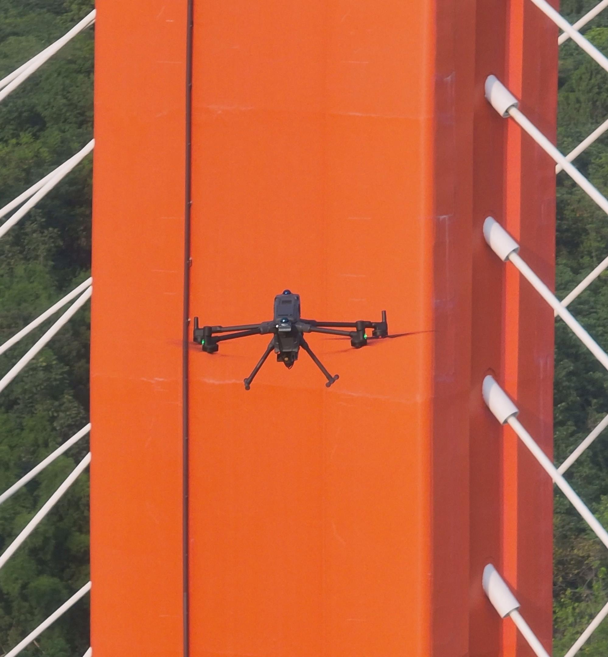
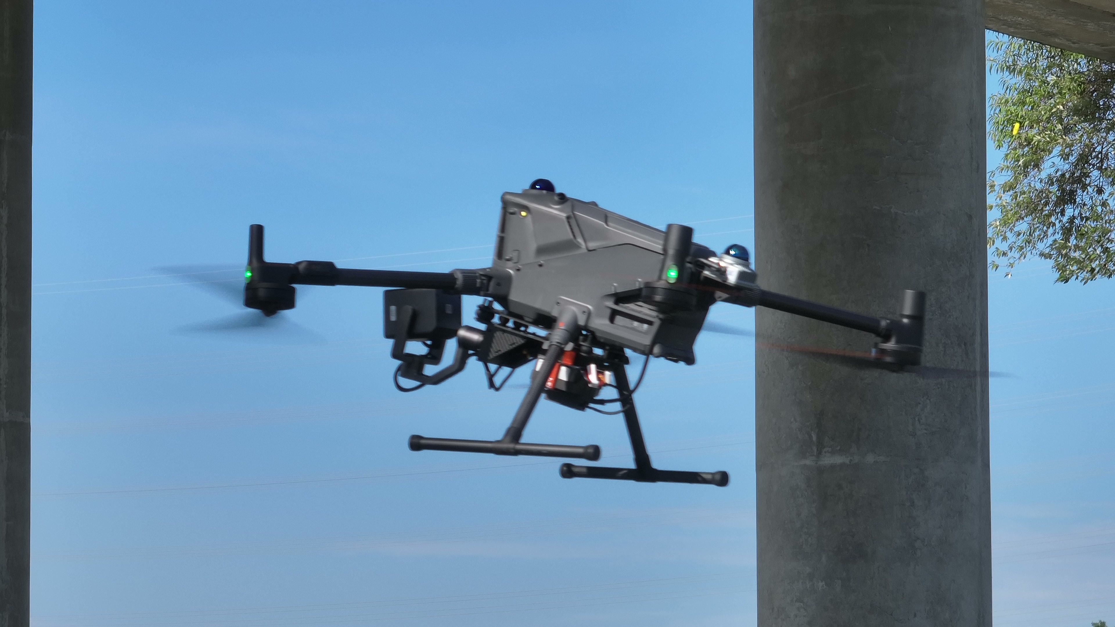
Capture imagery beneath decks, around tall piers and near bearings where drone operation is suitable, reducing the need for personnel to approach hazardous areas.
Organize routes and capture tasks by bridge component and reuse validated missions to support consistent data collection across inspections.
Link photos, component locations and suspected defects so reviewers can locate issues, organize findings and prepare inspection reports.
Bridge inspection is more than flying a drone. Every capture must be planned, reusable and verifiable. The solution combines drone operations, under-bridge positioning, component-level route planning and high-resolution imaging. A 61-megapixel full-frame camera, laser ranging and fill lighting provide clear images for defect detection, professional review and result management, completing the inspection workflow.
Satellite signals are easily blocked beneath decks and around beam recesses, piers and abutments, making GNSS-dependent operations difficult to sustain.
Work at height, bridge-inspection vehicles and waterside operations are complex to organize, while some blind spots remain difficult to approach safely.
Manual control can produce inconsistent distance, angle and clarity, reducing comparability between inspection cycles.
Without a unified link between large image sets, components and defects, review, localization and reporting become costly.
From flight platform to data platform, every module works along the same inspection mission chain.
The M400 supports long-endurance, detailed inspection of large areas such as major under-bridge girders and high piers, while the M4 extends coverage to confined spaces such as bearings and gaps between adjacent piers.
A 61-megapixel full-frame camera combines laser ranging, precise focusing and fill lighting to support fine-crack detection and crack width and length measurement.
Integrated positioning, perception and navigation support continuity between above-bridge and under-bridge operations.
Import the 3D bridge model and plan routes, waypoints and capture actions covering target components.
Configure mission and camera parameters while monitoring route execution, flight status and capture progress.
Manage missions, components, images and defects in one place, supporting detection, review, localization and reporting.
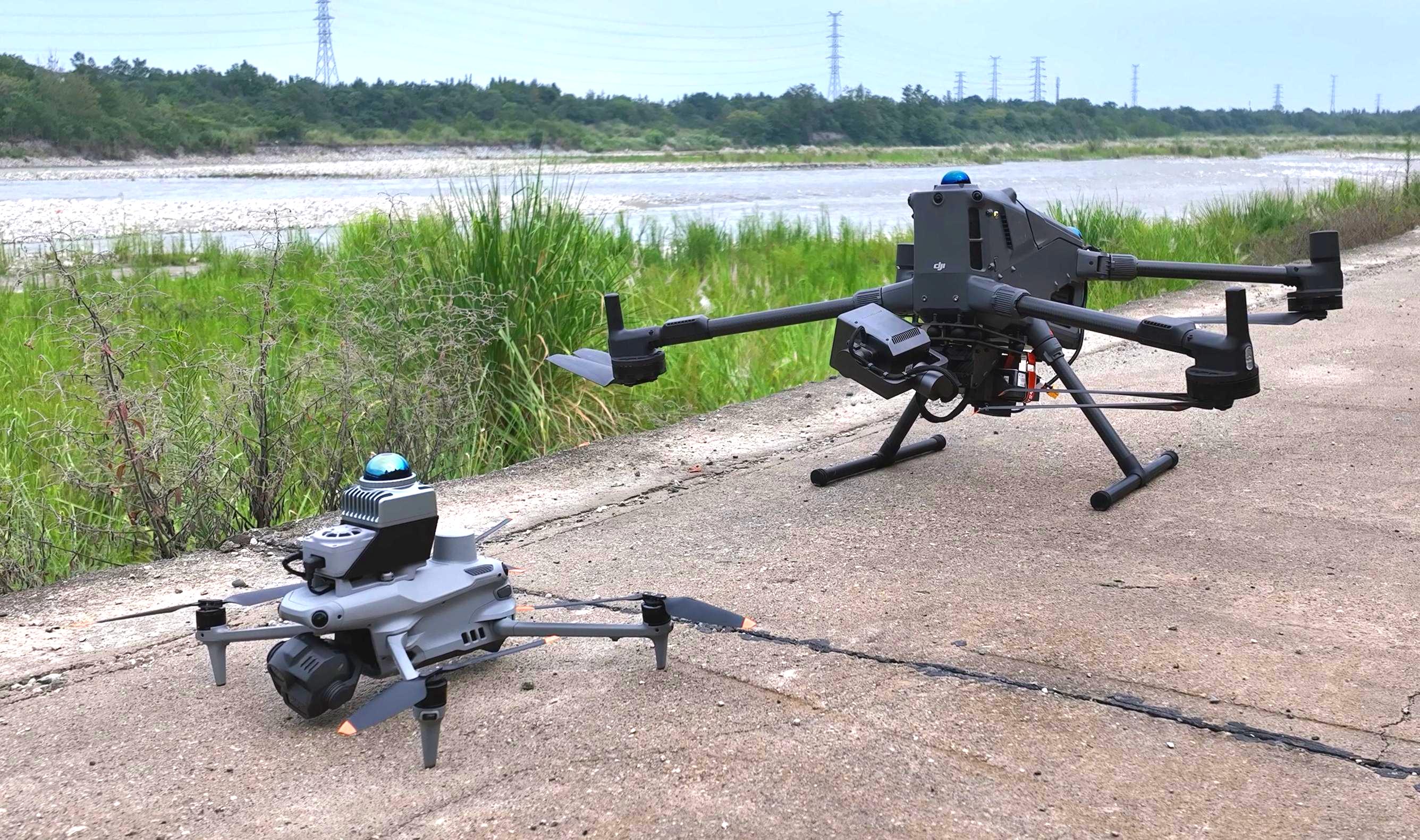
The two aircraft are configured together according to component scale and accessible space, balancing large-area detailed capture with local close-range inspection while maintaining mission continuity.
Designed for large inspection areas requiring long endurance and high-precision capture, including major under-bridge girders and high piers.
Designed for bearings, spaces between adjacent piers and other areas the M400 cannot enter or approach closely.
Both M400 and M4 carry the INES onboard navigation module, enabling seamless switching between satellite positioning in open areas and GNSS-denied positioning beneath bridges.
The dedicated bridge imaging system combines a full-frame camera, laser ranging and fill lighting. From clear images to dimensional measurement, it provides evidence for defect detection, professional review and maintenance records.
A 61-megapixel full-frame camera delivers a spatial resolution of 0.05 mm and detects 0.1 mm cracks at a capture distance of 4 m, preserving fine surface-defect details on bridge components.
Laser ranging measures the target distance to assist precise focusing. Distance and image data are combined to calculate crack width and length, supporting dimensional measurement and subsequent review.
Built-in fill lighting illuminates the target surface in low-light conditions beneath bridges and in strong backlighting, helping capture clear images and preserve details in shadowed areas.
Spatial resolution, crack detectability and dimensional measurement accuracy are different metrics. Imaging and measurement results depend on lens configuration, capture distance, angle, lighting and flight stability. Defect measurements require professional review.
Bridge inspection moves across open deck areas, girder undersides and piers with very different satellite-signal conditions. INES fuses RTK, LiDAR SLAM and inertial data to maintain continuous aircraft pose as positioning conditions change. It executes KML inspection missions generated by ARP onboard, keeping positioning, flight and image acquisition coordinated.
RTK provides the position reference in open deck areas. When satellite signals weaken beneath the bridge, positioning transitions to LiDAR SLAM, reducing the impact of positioning-source changes on mission continuity.
An integrated point-cloud map and LiDAR SLAM provide stable position and attitude references for close inspection of girder undersides, piers and bearings.
INES parses and executes routes, waypoints and actions exported by ARP, coordinating the aircraft, gimbal and camera so that routes, viewing angles and capture actions are more consistent across repeat inspections.
INES records waypoint and action progress, supports resuming from an interruption or selected waypoint, and reports position, attitude, positioning source and camera status to AGS so operators can continuously monitor the mission.
5–10 cm is the typical LiDAR SLAM positioning accuracy. Actual performance depends on the point-cloud map, bridge geometry, sensor configuration, installation calibration, flight speed and environmental conditions, and is subject to project-site testing.
Explore the INES Onboard Navigation Module ↗ARP brings the 3D bridge model, component annotation, route calculation and capture-action setup into one workspace. After target components, drone type, inspection distance and image overlap are selected, it generates candidate routes and waypoints for preview, review and adjustment before field execution.
Explore ARP Bridge Route Planning ↗Import a 3D bridge model and annotate target components such as piers, girders and arch ribs.
Calculate candidate waypoints from component geometry, inspection distance, overlap and drone type.
Review routes and actions, export a KML mission and hand it to AGS for field execution.
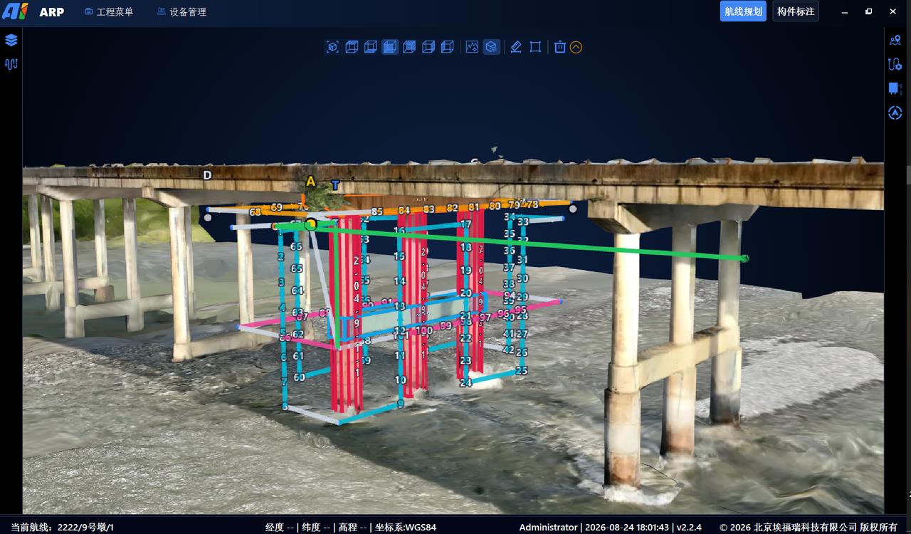
Generated routes must be reviewed against site surveys, obstacles, airspace, weather and drone performance limits, followed by real-aircraft validation.
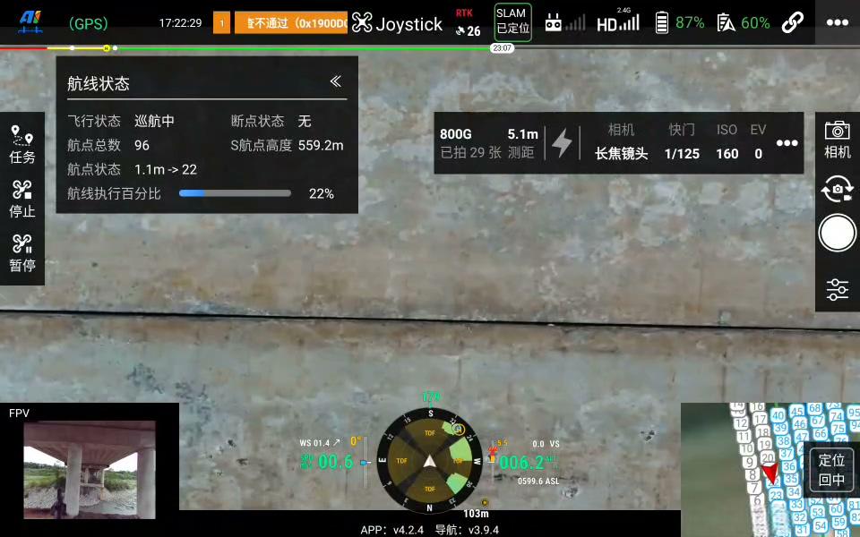
AGS centralizes route missions, camera parameters and flight status at the ground station, helping operators execute inspections through a standard workflow.
Explore AGS Drone Ground Station Software ↗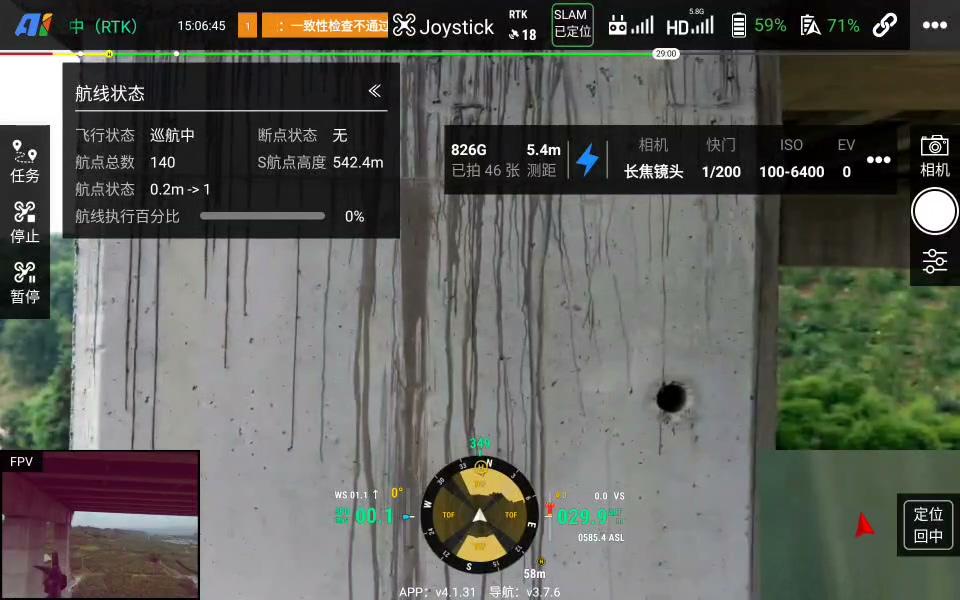
The inspection platform links missions, components, high-resolution images and suspected defects. AI assists screening, while professionals annotate, verify and revise results and view defect locations in 3D.
Detection results assist inspection; final conclusions must be reviewed by suitably qualified professionals.
Explore the Bridge Inspection Platform ↗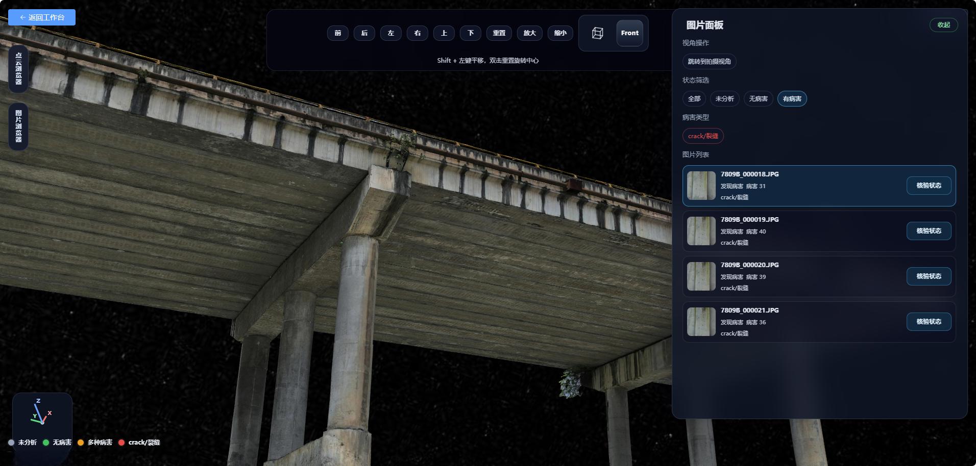
Use an existing BIM / 3D model or field data as the basis for route planning.
Configure routes and capture actions for the deck, bridge sides, girder underside, piers, abutments and bearings.
Import the mission into AGS, confirm field safety conditions, then execute the inspection and monitor progress.
Collect images and position data, creating traceable relationships by mission and component.
AI assists with screening suspected defects; professionals annotate, confirm and revise the results.
View defect distribution in 3D, compile statistics and generate reports to project requirements.
Onboard positioning based on LiDAR SLAM and related sensing provides stable positioning in GNSS-denied under-bridge environments.
The dedicated bridge imaging system detects 0.1 mm cracks at a capture distance of 4 m, supporting defect detection and professional review.
For obstructed environments such as bridge undersides, onboard positioning and perception provide 5–10 cm positioning accuracy to maintain operational continuity.
Organize detailed capture for girder undersides, webs, piers, cap beams, bearings and other components.
Reuse missions and routes to keep capture positions and viewpoints as consistent as possible between inspection cycles.
Trace suspected defects to their components and spatial locations, shortening the reinspection path.
Create standardized, reusable periodic inspection data for conventional girder and urban bridges.
Capture elevated, under-bridge and waterside areas of cable-stayed, suspension, arch and other complex bridges.
After a disaster or abnormal indication, provide imagery for priority-area review and subsequent professional inspection.
Projects cover highway, urban and elevated rail bridges in environments including mountainous high-pier sites, river crossings, coastal crossings and built-up urban areas. Real-world work continuously validates route planning, under-bridge operations and data capture.
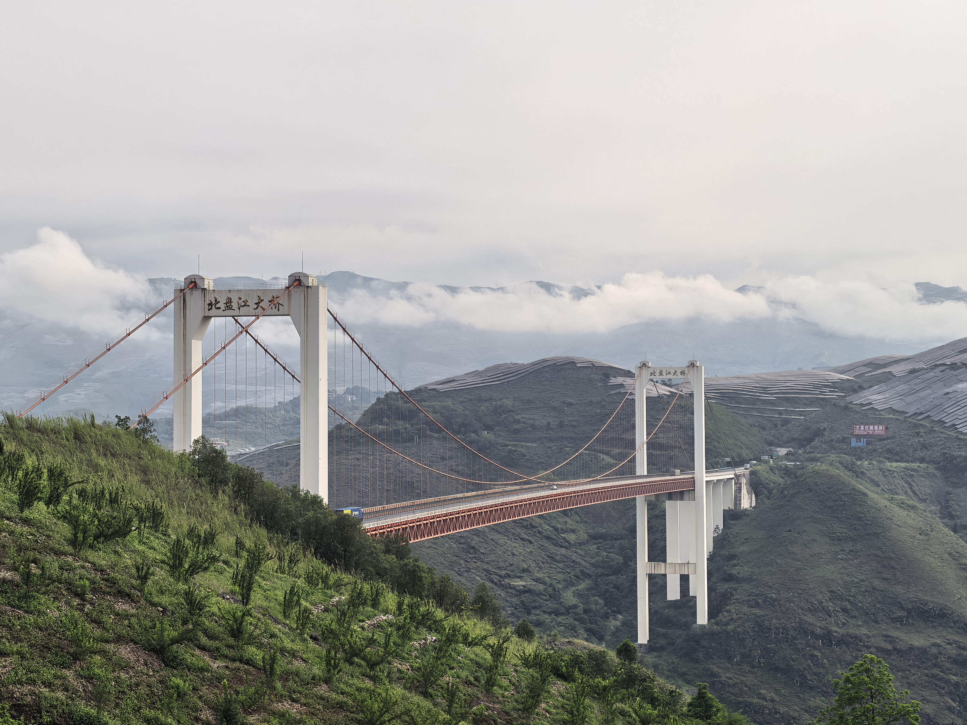
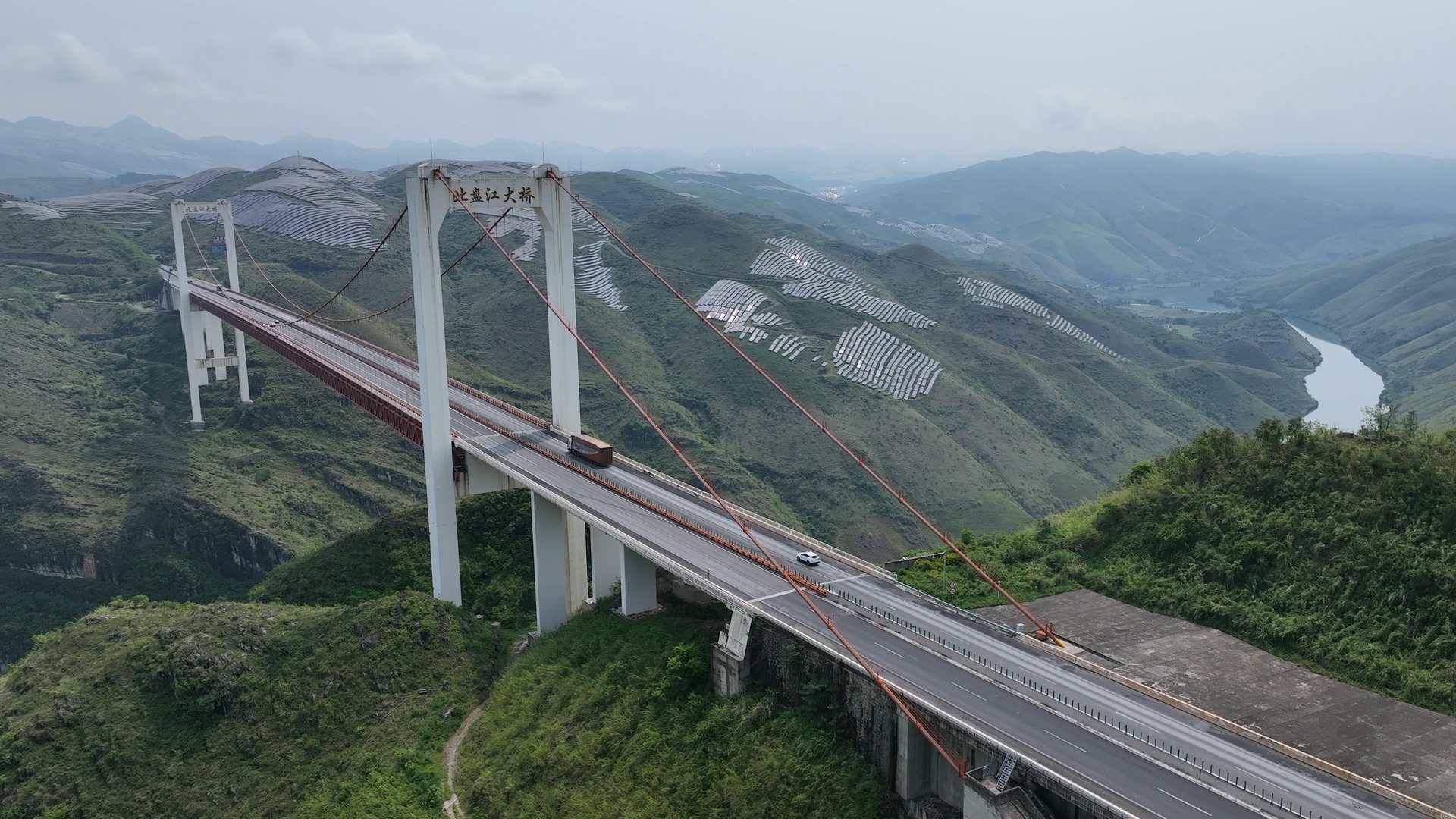
For deep valleys, large elevation differences and very long spans, multi-directional imagery covers towers, main cables, deck systems and bridge sides, demonstrating adaptability to complex structures and terrain.
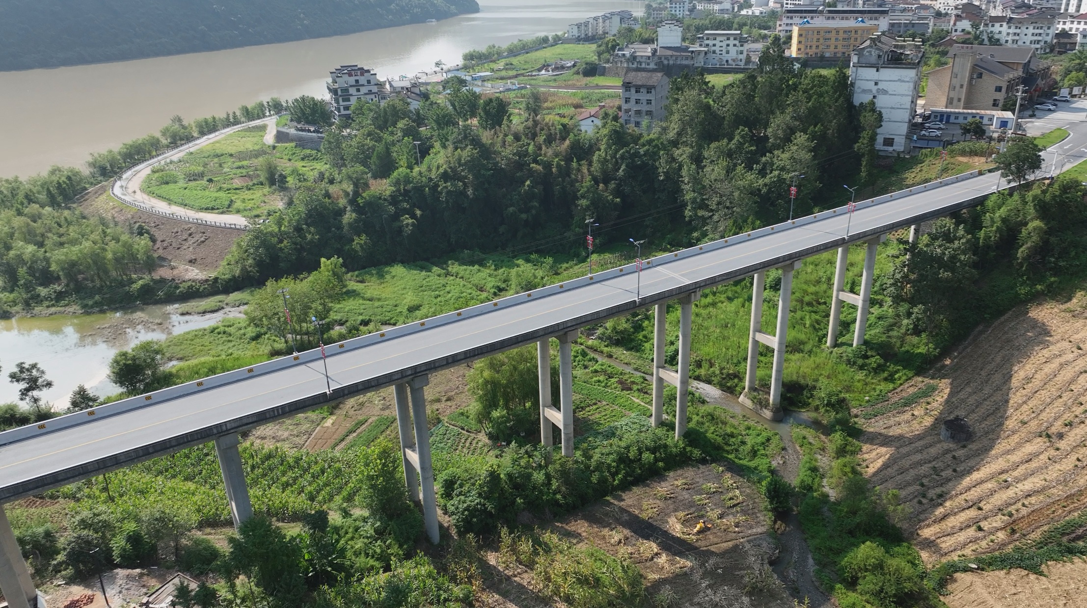 01
01Multi-view capture of the overall bridge and priority components in valley terrain and long continuous spans.
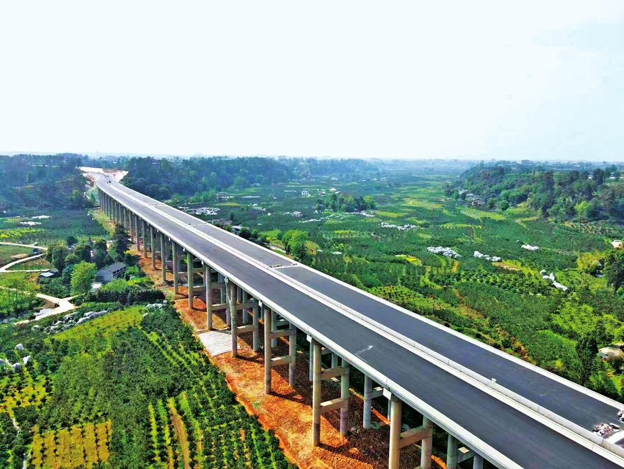 02
02Repeatable segmented missions organized around continuous spans and the surrounding corridor.
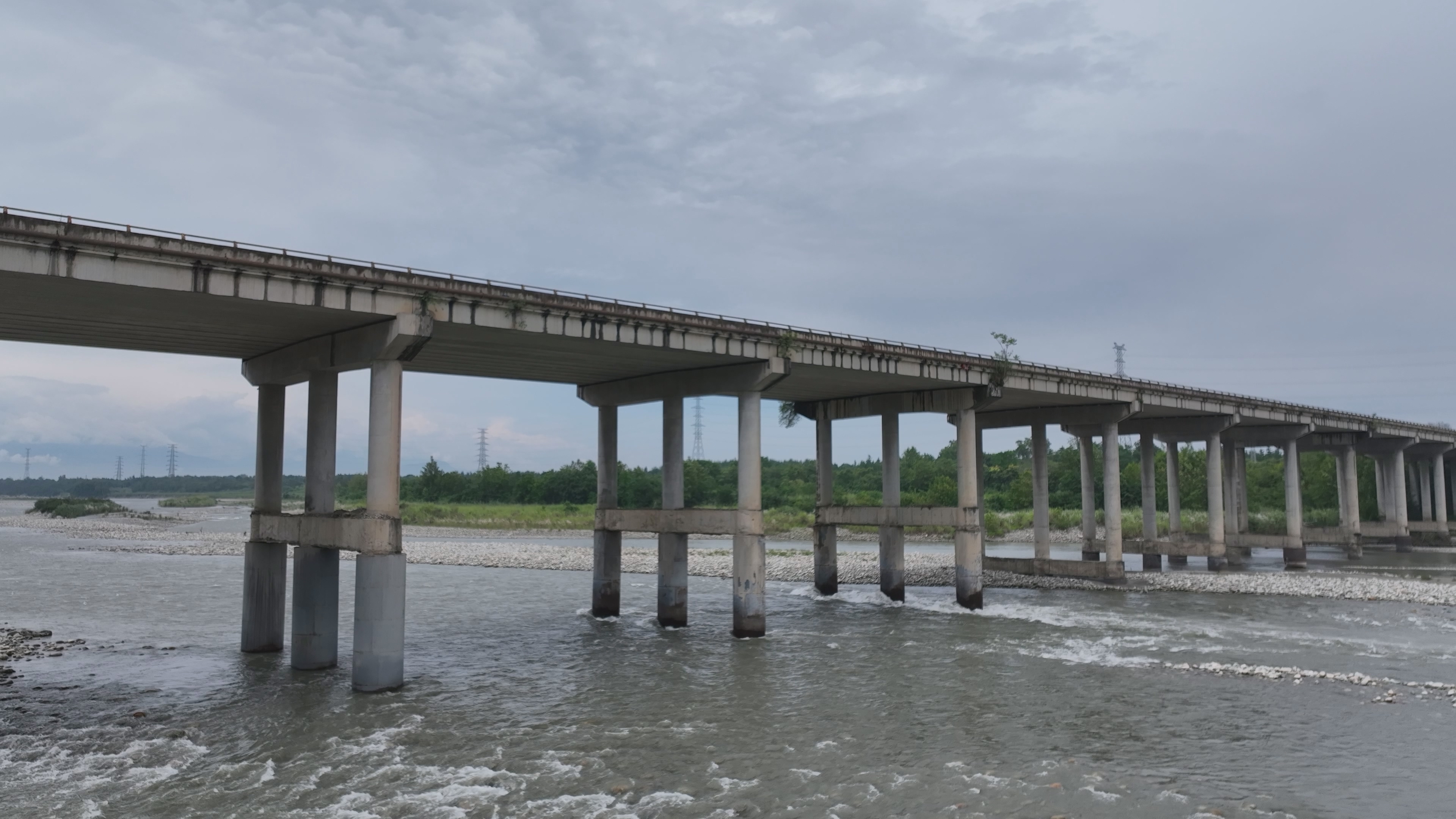 03
03Typical inspection views covering the deck, bridge sides, girder underside and waterside components.
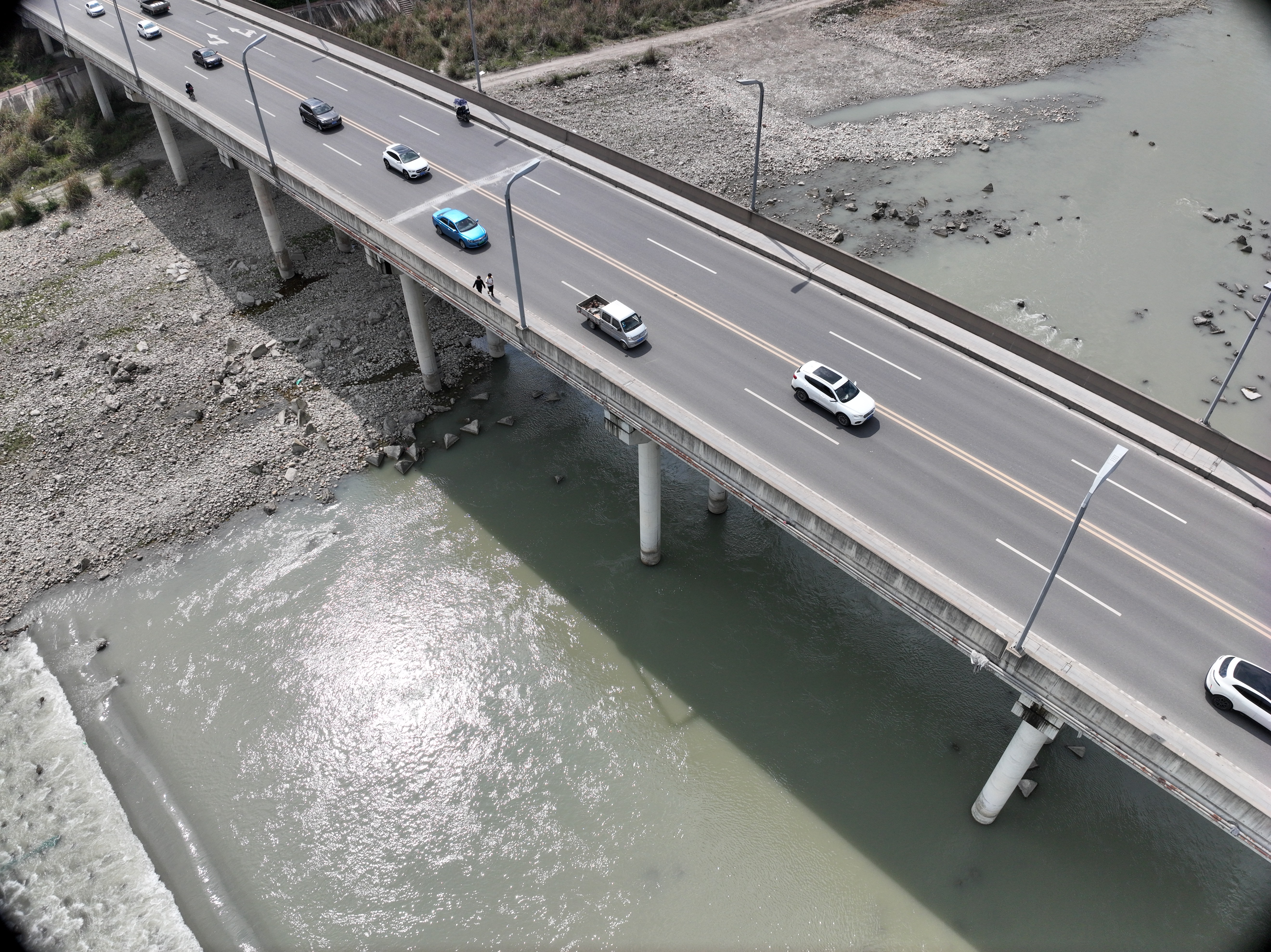 04
04Capture paths planned around spans, piers and girders in river and high-elevation-difference conditions.
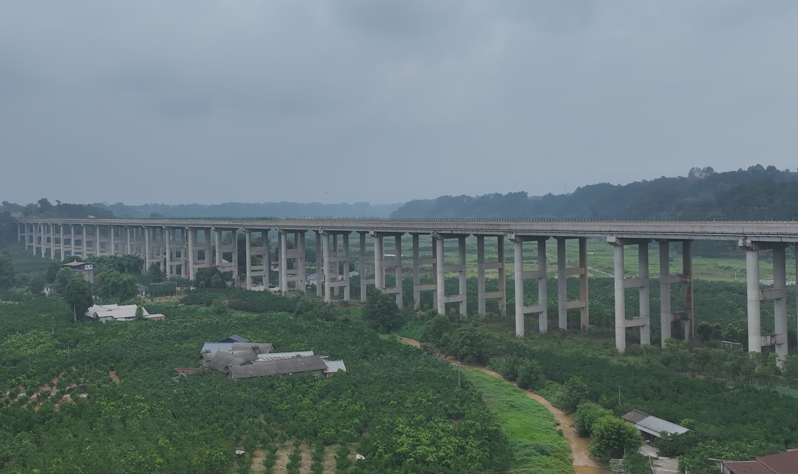 05
05Field inspection organized for long distances, high piers and mountainous obstruction.
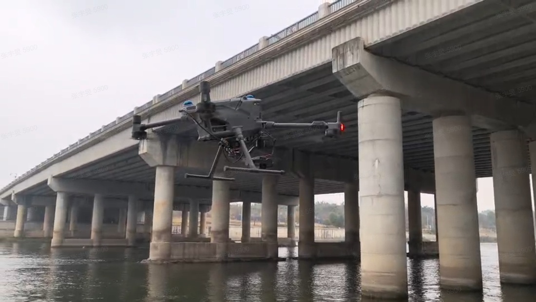 06
06Close-range drone capture beneath the bridge validates operational reach in complex spaces.
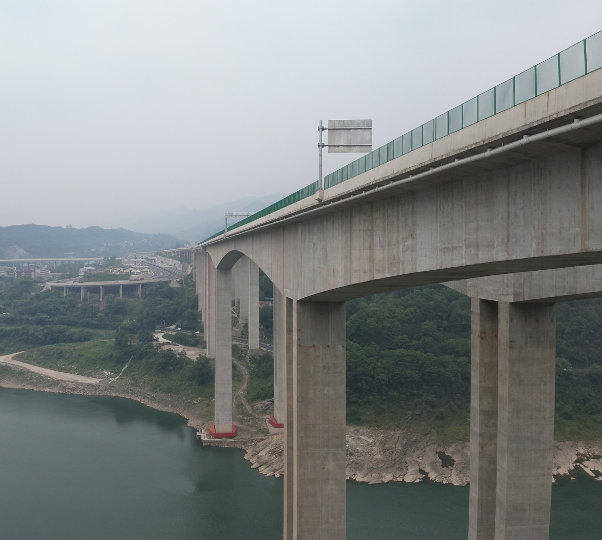 07
07Multi-directional capture in bridges with large elevation differences, waterside exposure and constrained terrain.
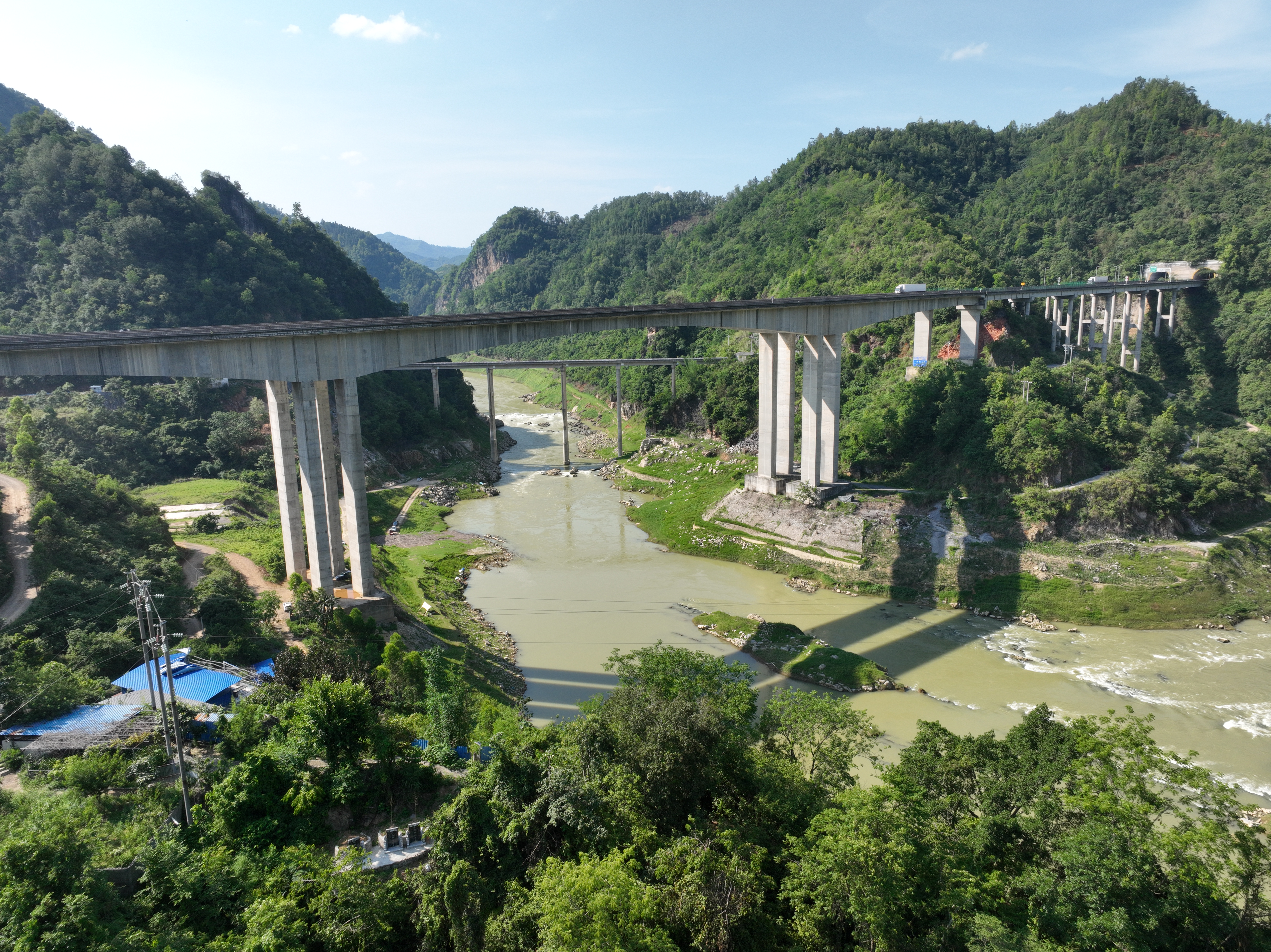 08
08Overall and component-level inspection organized around high piers, long spans and valley conditions.
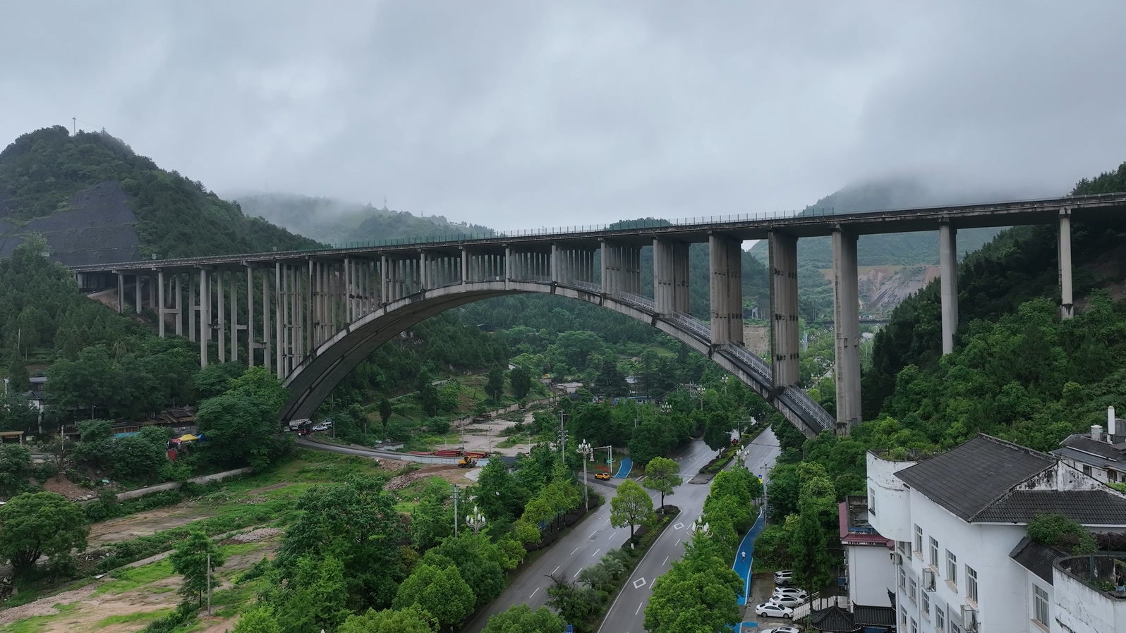 09
09Capture viewpoints planned for arch rings, columns, deck systems and other structural directions.
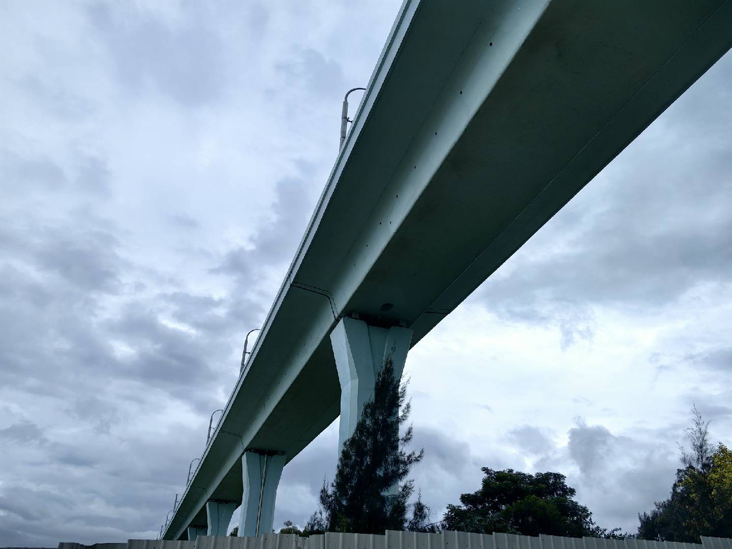 10
10Inspection data capture focused on girder undersides, piers and track direction in a coastal environment.
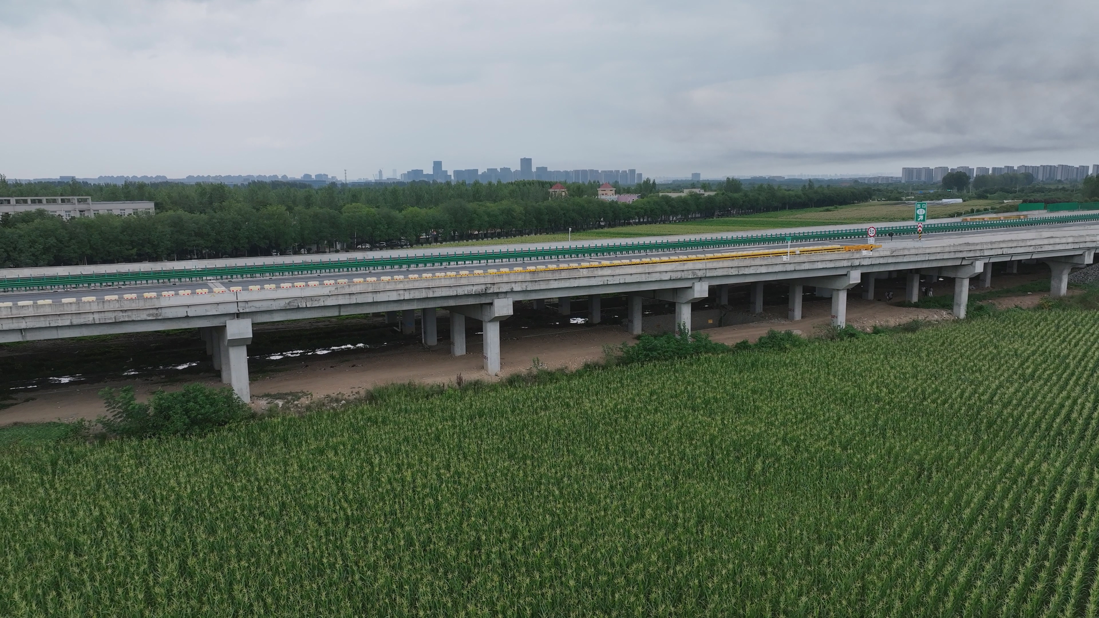 11
11Standardized, zoned field capture for a multi-span bridge on an operating corridor.
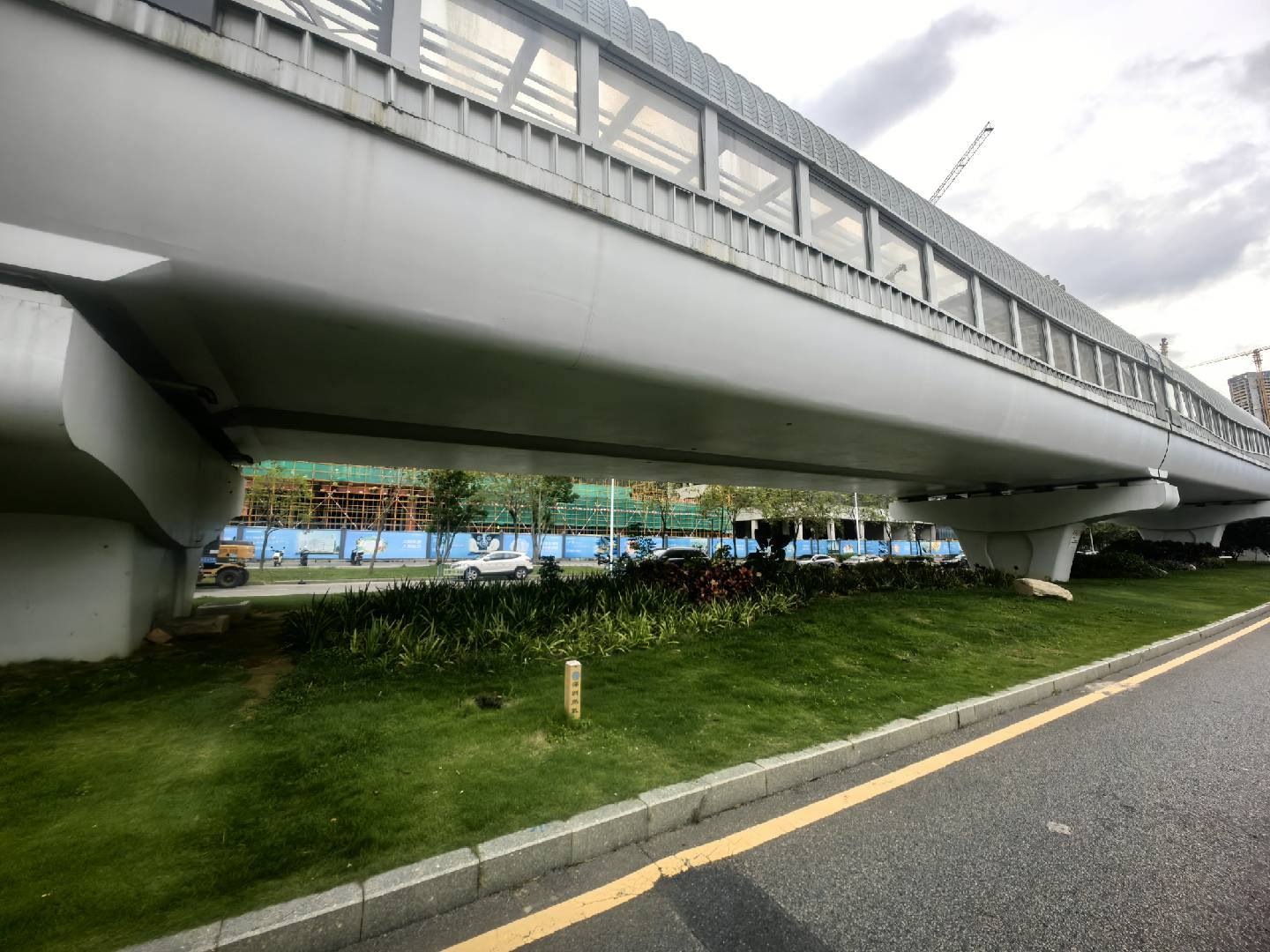 12
12Close-range capture of girder undersides, support zones and side components in an urban environment.
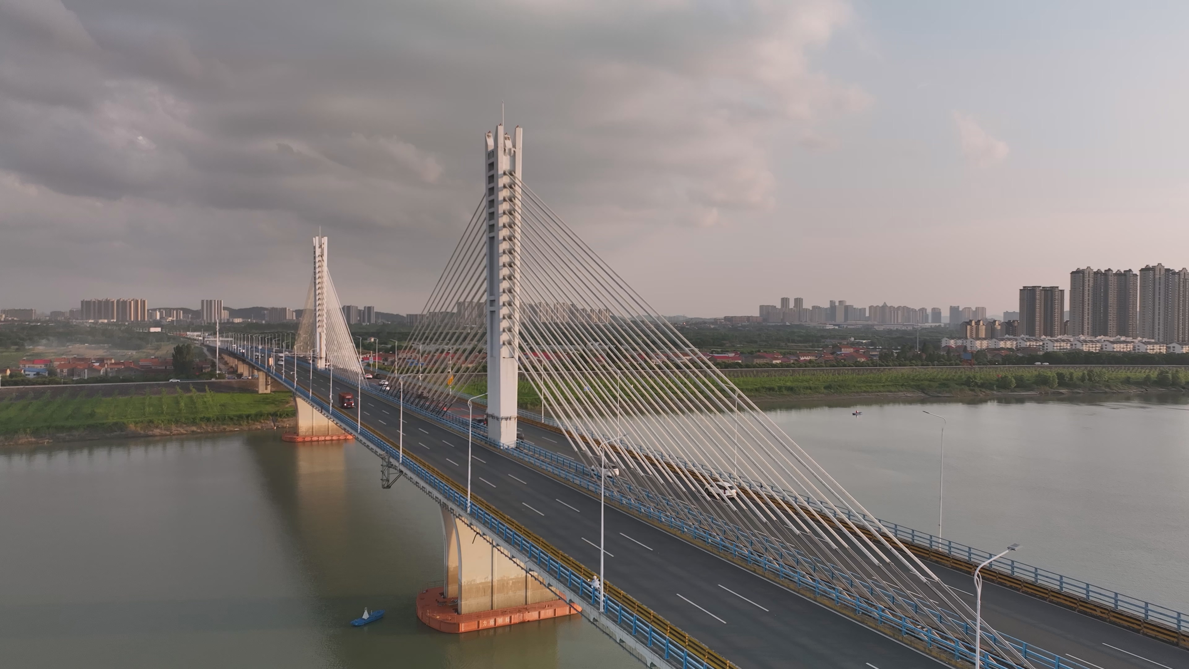 13
13Coverage of towers, stay cables, deck systems, waterside zones and other representative structures and environments.
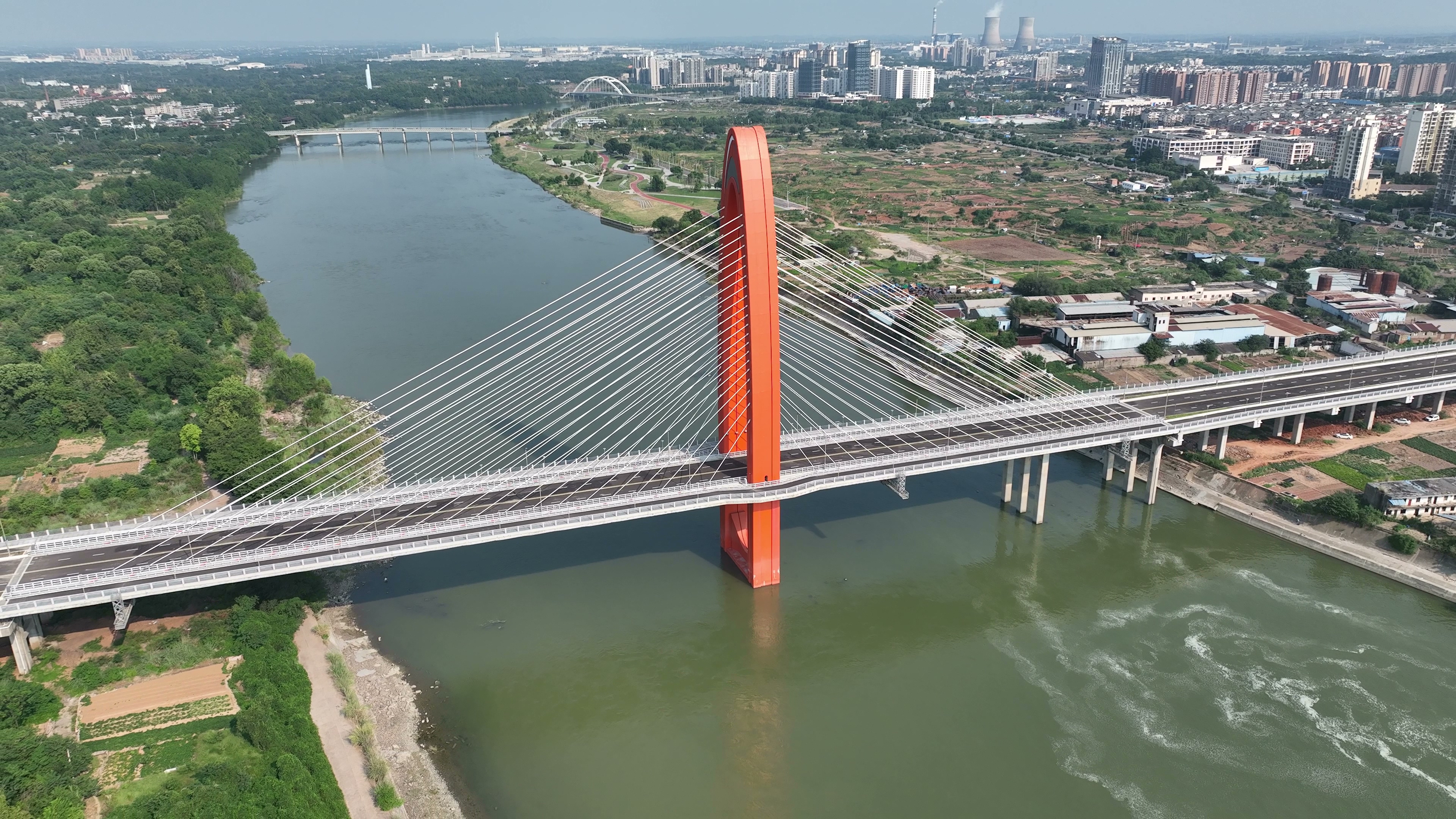 14
14The main tower, stay cables and spans illustrate the site conditions for component-level inspection of a river-crossing cable-stayed bridge.
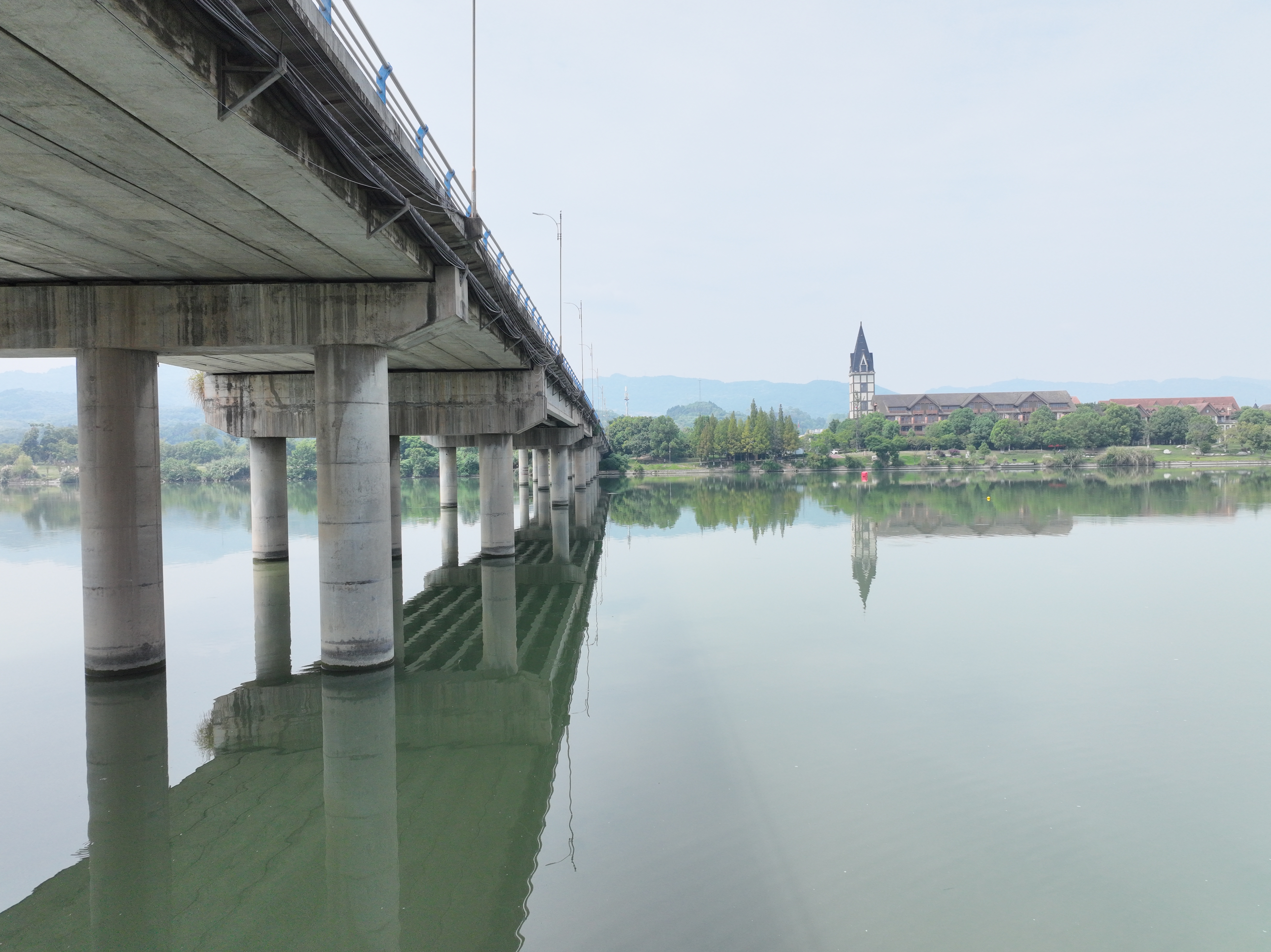 15
15The girder undersides, piers and waterside setting illustrate the site conditions for under-bridge inspection.
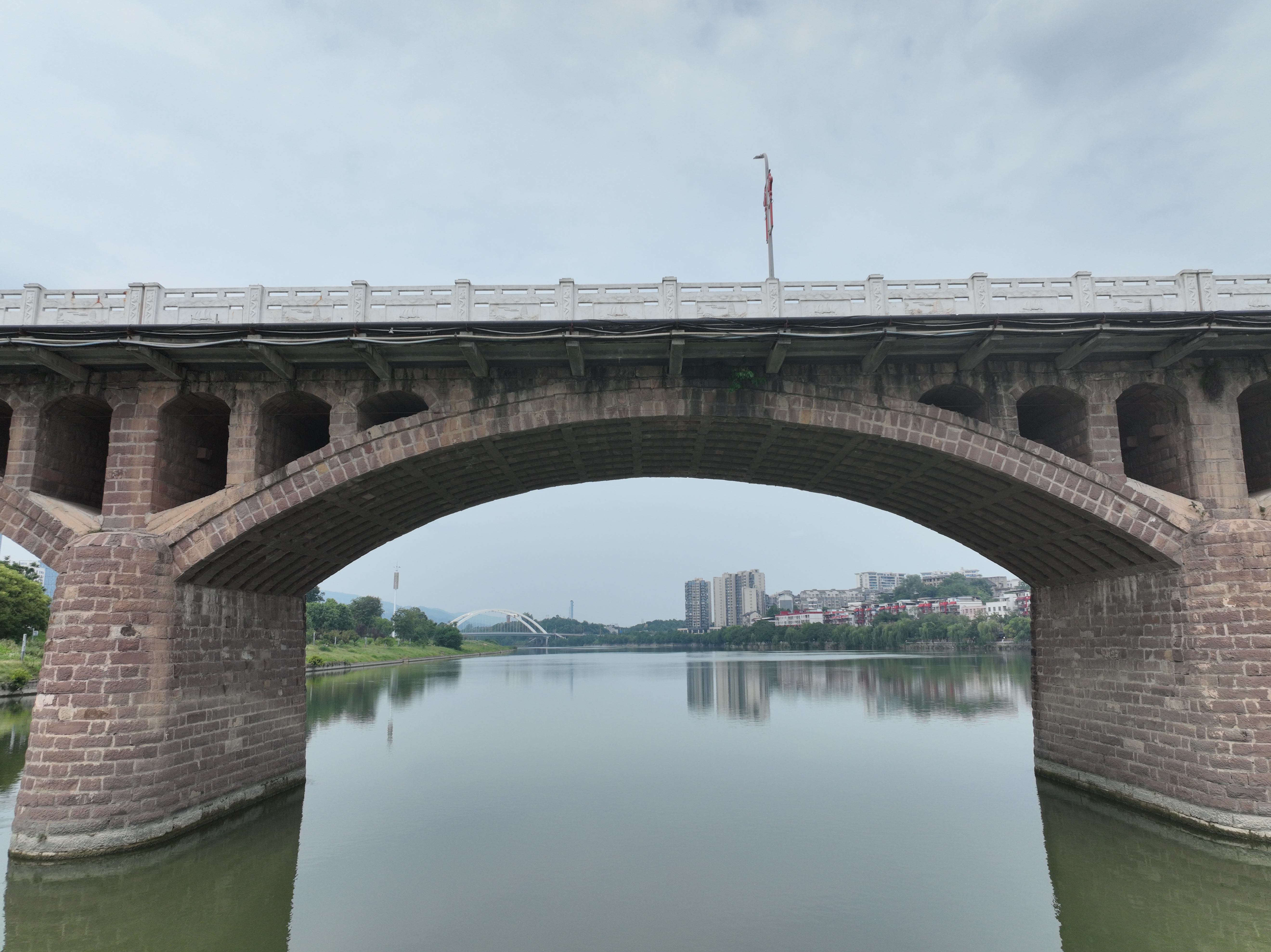 16
16The relationship between the arches, supports and water surface illustrates the site conditions for arch-bridge component inspection.
Images show selected engineering practices and field environments. A single image does not represent the complete scope of a project; configuration depends on actual requirements and the approved technical solution.
Configure the right equipment and software for the bridge type, component scope, operating environment and deliverable requirements.
Last updated