Turbine Parameter Management
Stores tower-center coordinates, tower height, blade length and other mission data by turbine for quick field selection.
 Contact Us ↗
Running on a professional smart controller for rotating-blade drone inspection, Wind AGS unifies turbine-parameter management, mission setup, onboard route-generation coordination, laser-triggered capture, status monitoring and manual intervention.
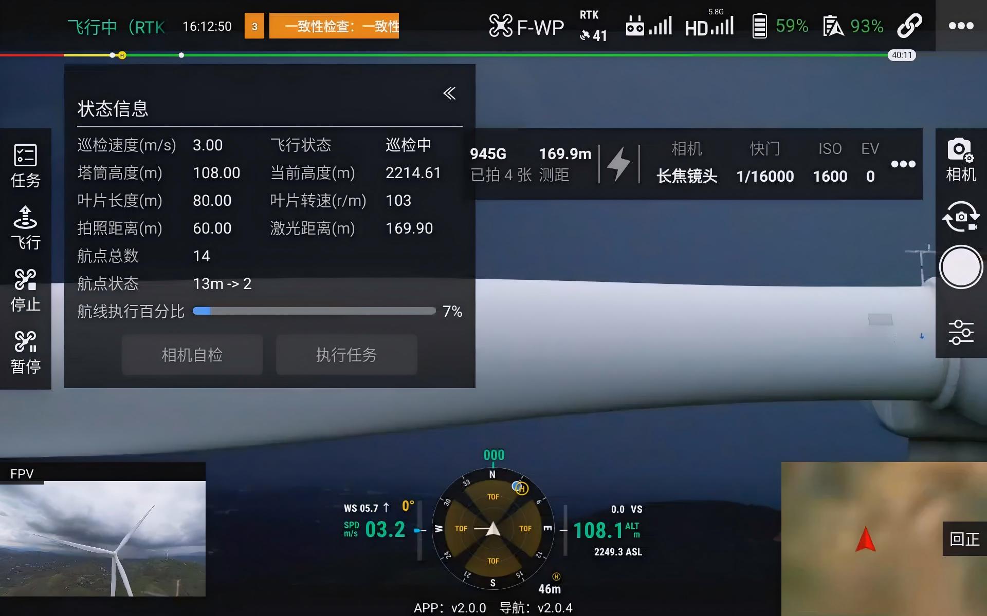
Wind AGS organizes missions around tower and blade geometry, with a dedicated workflow for continuously rotating blades, short capture windows and numerous turbines.
It handles controller-side parameter input, mission configuration, status display and manual intervention. Onboard INES calculates and executes routes, while acquired data enters the Wind Inspection Platform for AI suspect screening, professional review and reporting.
Stores tower-center coordinates, tower height, blade length and other mission data by turbine for quick field selection.
Dispatches turbine and inspection parameters to INES, which generates and executes the route from geometry.
Continuously displays mission progress, flight, positioning, battery, camera and ranging information during rotating-blade inspection.
Configures a ranging trigger zone so the camera captures when a blade enters the specified distance range.
Mission parameters and safety thresholds must be confirmed against aircraft, payload, wind, turbine status and site procedures. Automation does not replace pilot monitoring.
Select a target turbine from the parameter library and load confirmed tower and blade values.
Configure inspection speed, imaging distance, overlap and blade safety distance.
Set exposure, focus and laser-trigger range for lighting and imaging requirements.
AGS dispatches parameters and INES calculates a route for the current turbine onboard.
The aircraft maintains the mission-defined relative imaging position while laser ranging supports capture triggering.
The pilot continuously monitors status and alerts and pauses, stops or takes over when needed.
After turbine selection, AGS loads associated geometry and mission parameters and checks imaging distance, inspection speed, blade speed, range and camera status before start.
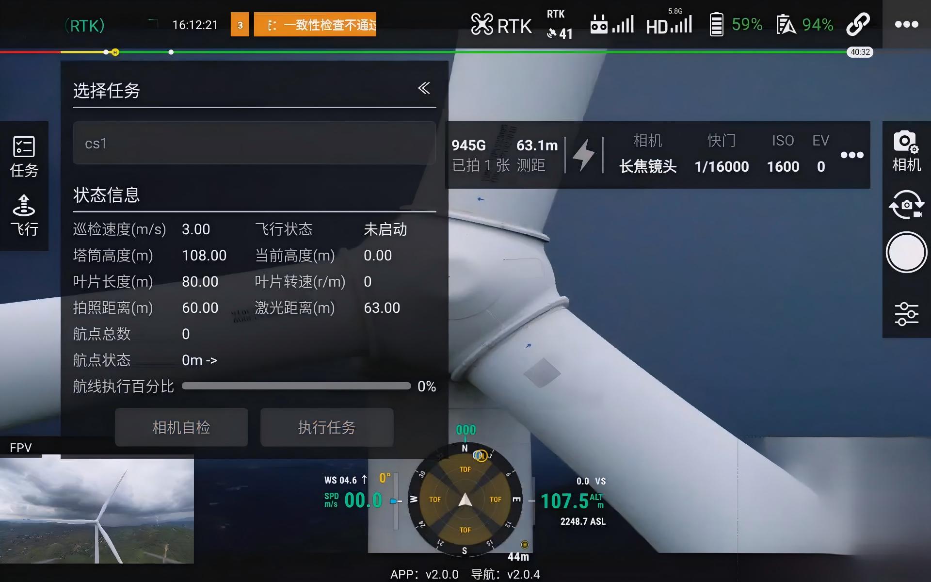
AGS sends turbine and inspection parameters to INES, which generates and executes the route onboard; the pilot continuously monitors imagery, distance and progress.
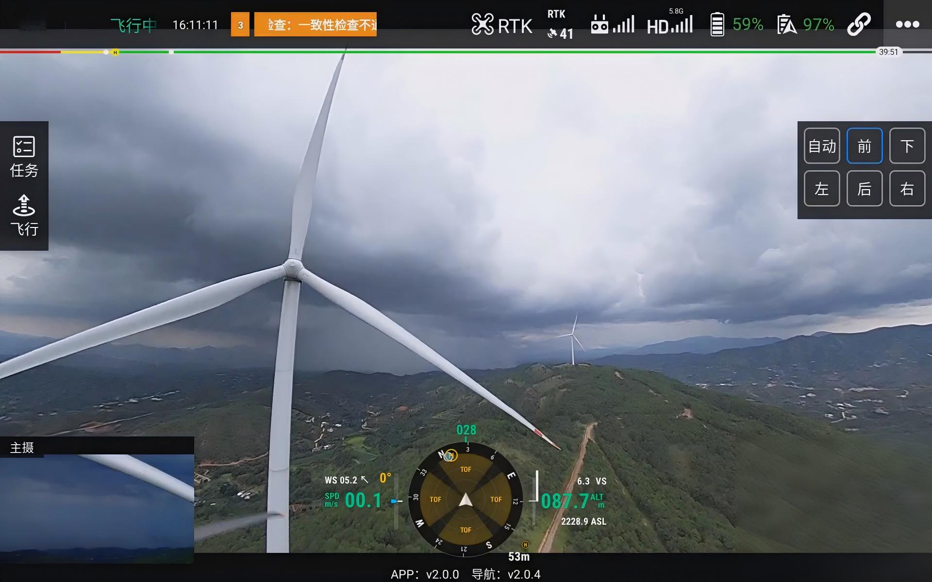
The mission defines acquisition coverage by blade length and uses preset distance and overlap for blade-surface imaging.
Displays ranging and alerts in real time to support distance judgment and exception handling in a dynamic environment.
Retains status confirmation, pause, stop, return and manual takeover during automated execution.
When laser range enters the preset minimum/maximum interval, capture can be triggered by the integrated logic. The range must consider focal length, clarity, blade scale and flight safety.
Trigger performance depends on camera, ranging capability, blade material, attitude, lighting and communication latency and requires phased testing before delivery.
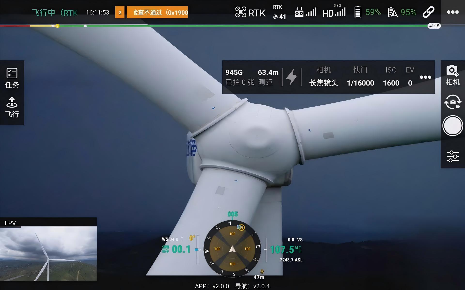
Key status is centralized to help the pilot judge whether the mission is on plan and when intervention is needed. Fields and controls vary with aircraft, controller, camera and software version.
Total Waypoints, Current Stage, Progress and Mission Status
Position, Attitude, Speed, Altitude, Battery, Link and Alerts
RTK, Positioning Quality, Connection and Mission Execution
Main / FPV Views, Camera Parameters, Images Captured and Remaining Space
Laser Range, Trigger Zone and Distance Alerts
High altitude, strong wind and rotating blades present continuous risk. Parameter alerts and automated strategies assist operations but do not replace site survey, weather judgment, procedures or pilot responsibility.
Use maximum/minimum thresholds to indicate deviation from the imaging range or excessive proximity.
Configure alert and intervention distances by aircraft and project and validate on site before execution.
Set alert and return conditions from mission reserve, wind and return distance.
Retain pause, stop, return and manual takeover and follow the site contingency plan.
Defines field operations, equipment configuration and delivery boundaries.
02 / EXECUTEReceives parameters, generates routes onboard and connects positioning with flight control.
Configures turbine missions and monitors dynamic inspection, capture and safety.
Organizes imagery, AI suspects, human reviews, history and reports.
Provide turbine model and parameters, aircraft and payload configuration, site wind and operating requirements, and we will help confirm the AGS integration plan.