Combine modes around the plan
Use dynamic inspection during operation and add detailed static work during planned shutdowns.
 Contact Us ↗
Match inspection to maintenance goals through downtime, coverage and reporting requirements.
For wind-farm blade surface inspection, drone imaging reduces the need for some manual work at height and connects planning, capture, defect review and reporting. Use dynamic inspection during operation and detailed static inspection in planned shutdown windows, combining them to meet maintenance goals.
Use dynamic inspection during operation and add detailed static work during planned shutdowns.
Static results link blades, surfaces and defect locations to support follow-up and maintenance.
Standardize missions and imagery, retain history and compare inspections where attribution is reliable.
Use dynamic inspection during generation, then static inspection in planned shutdown windows to add head-on leading-edge imagery and records for individual blades.
Turbine running: no inspection-related shutdown or associated generation loss
For routine and periodic inspection without shutdown.
Centimetre-scaleTurbine stopped and blades locked: requires downtime with generation loss
For planned maintenance shutdowns, leading-edge inspection and detailed blade records.
Millimetre-scale| Comparison | Dynamic Inspection | Static inspection |
|---|---|---|
| Operating state and generation impact | Turbine running: no inspection-related shutdown or associated generation loss | Turbine stopped and blades locked: requires downtime with generation loss |
| Image coverage | Clear pressure- and suction-side imagery; side views of the leading edge, but no head-on views | Inspection imagery covering the pressure side, suction side and leading edge of all three blades |
| Defect identification scale | Centimetre-scale | Millimetre-scale |
| Blade attribution | Cannot reliably attribute defects to actual numbered blades | Distinguish all three blades and attribute defects to the specific blade |
| Capture trigger | Laser-triggered capture | Planned waypoint capture |
| Mission organization | Continuous multi-view capture | Nine segments joined into one route for a single inspection sortie |
Defect scale is not measurement accuracy or a guarantee of detecting every defect type. Identification and single-sortie capability depend on defect type, distance, lighting, wind, aircraft payload and endurance, subject to project configuration and validation.
Where field conditions allow, multi-view capture provides clear pressure- and suction-side images. A 100 MP medium-format camera, high-speed global shutter and laser triggering support centimetre-scale defect identification on rotating blades without inspection-related shutdown losses.
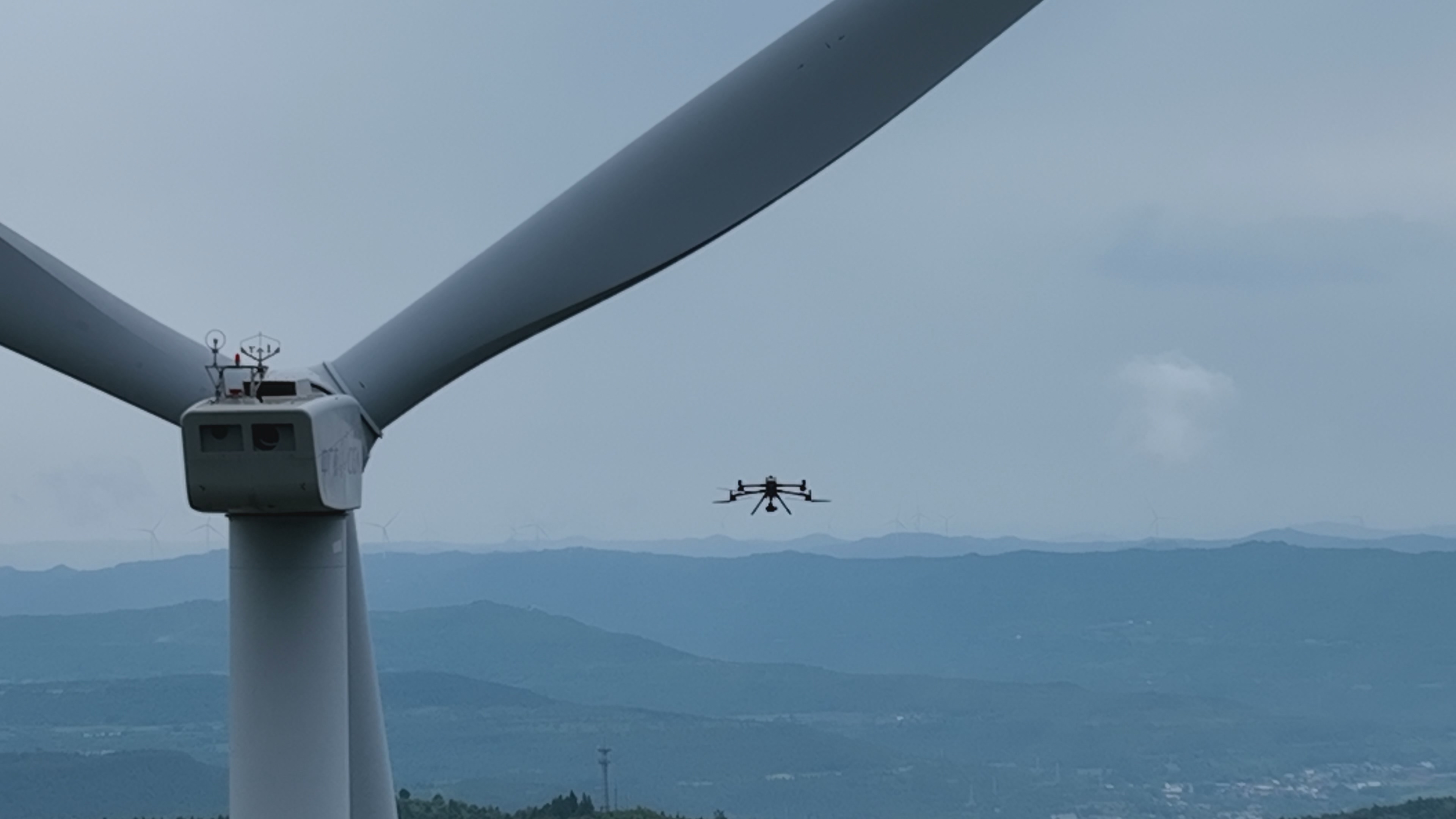
With the turbine running, the drone follows planned routes for multi-view capture. Laser ranging measures blade distance and laser triggering controls capture timing. A 100 MP medium-format camera with a high-speed global shutter captures clear pressure- and suction-side images. Waypoint photography cannot replace laser triggering in this mode.
Dynamic inspection provides side views, not head-on views, of the leading edge. Defects cannot yet be reliably assigned to actual numbered blades. Dynamic capture requires laser triggering, not waypoint-triggered photography.
Static inspection first builds a model, then generates inspection routes. Pressure-side, suction-side and leading-edge segments for each of three blades form nine segments joined into one continuous mission. After modelling, one inspection sortie can cover them when operating and endurance conditions permit, supporting millimetre-scale defect identification and blade attribution.
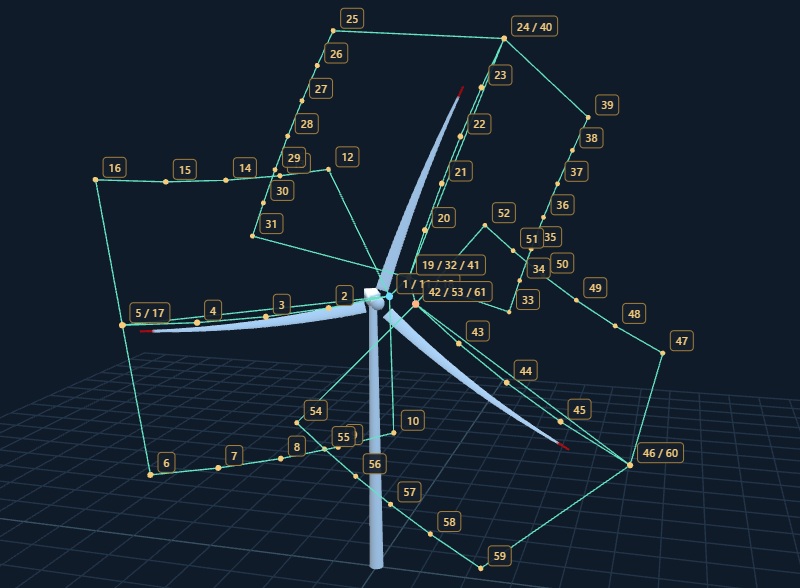
Three blades × pressure side, suction side and leading edge = nine inspection segments. Capture at planned waypoints and confirm blade-number correspondence. The single sortie refers to inspection after modelling, excluding model preparation.
A shared drone, imaging, navigation, ground station and results platform use planning and capture mechanisms suited to each inspection mode.
Carries navigation and imaging equipment to execute route flight and waypoint capture around turbines.
A 100 MP medium-format camera and high-speed global shutter support laser-triggered or waypoint capture.
Plan from turbine parameters or models and use RTK to coordinate flight and gimbal-camera control.
Configure missions, monitor flight and capture, and coordinate distance alerts and pauses with INES.
Organize and stitch imagery, assist defect identification, and support review, reports and history.
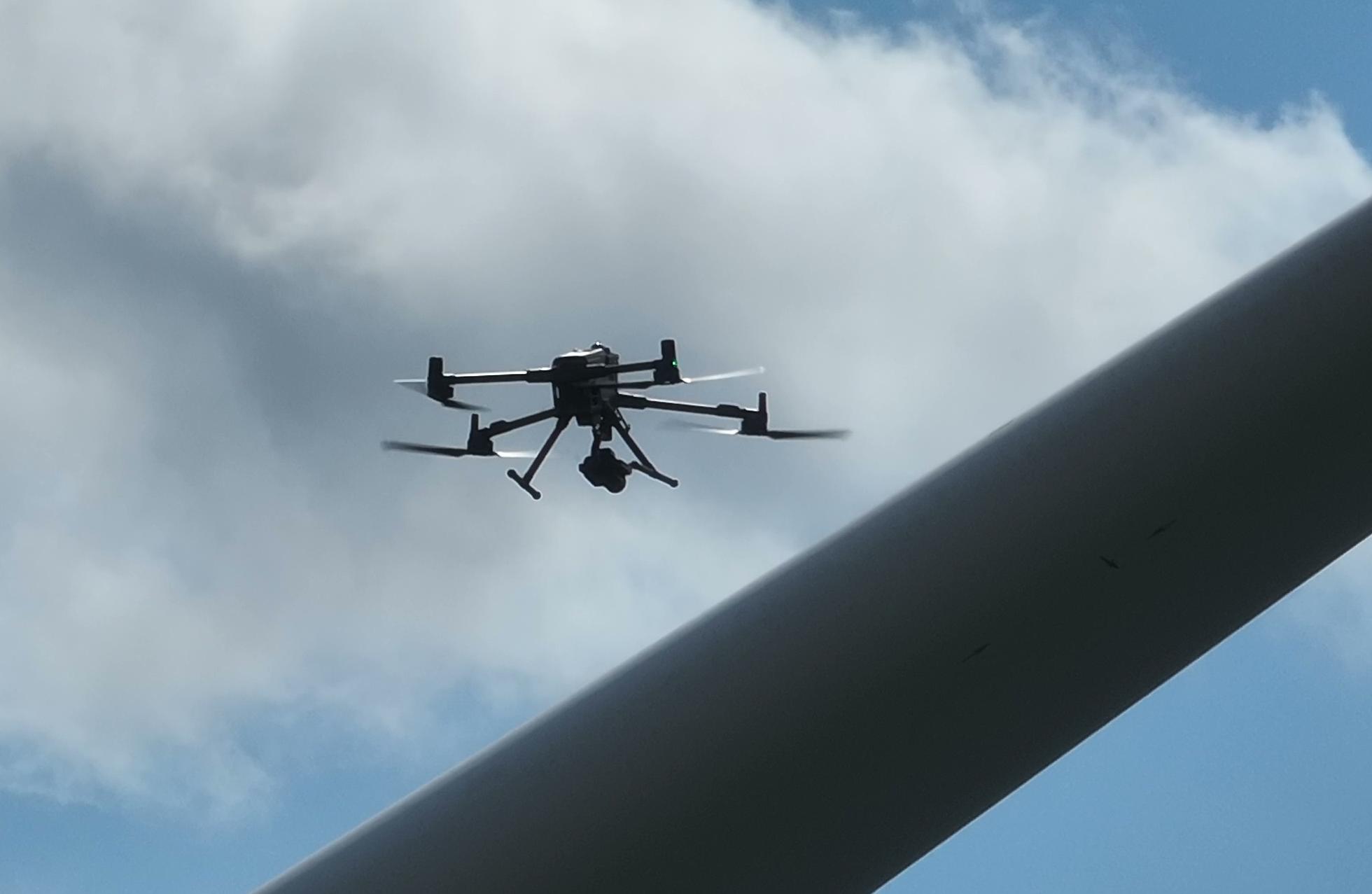
The DJI M400 carries INES onboard navigation and high-resolution imaging equipment, connecting flight routes, imaging payloads and ground-based mission management to support wind turbine blade inspection.
Flight control and the gimbal work with INES navigation to execute routes and hovering tasks around the turbine, supporting image capture from different blade viewpoints.
AGS displays flight, link and battery status to support sortie and return planning based on mission scope. Platform obstacle avoidance and return-to-home functions assist field response while retaining human intervention when needed.
Flight endurance, payload combinations and wind resistance depend on equipment configuration and mission conditions. Confirm wind, obstacles and safe blade clearance before operations. Obstacle avoidance and return-to-home functions do not replace site risk assessment.
The 100 MP medium-format system supports both modes: a high-speed global shutter and laser triggering capture rotating blades; static inspection captures images at model-planned waypoints.
A 100-megapixel medium-format camera captures clear blade-surface images while maintaining a safe distance from the turbine as confirmed through site assessment, balancing detailed imaging with operational safety.
A high-speed global shutter works with short exposures to capture clear images of fast-moving blades, particularly blade tips. This reduces motion blur and rolling-shutter distortion while preserving surface textures and suspected defect details.
Dynamic capture uses laser triggering; static capture follows planned waypoints. Capture timing and progress are organized for each mode.
Dynamic inspection requires site assessment of turbine model, blade rotational speed, wind, lighting, capture distance and exposure settings, with the operating plan approved by the wind farm. Safe clearance and image quality depend on the specific mission. Inspection without shutdown is not supported at arbitrary speeds or in all weather conditions. Defect assessments require professional review.
Configure turbine parameters and routes, and view attitude, link, battery, camera settings and capture progress. AGS works with INES to monitor blade clearance, alert and pause inspection flight when distance limits are exceeded, allowing operators to assess and respond.
Explore Wind-turbine Drone Ground Station Software ↗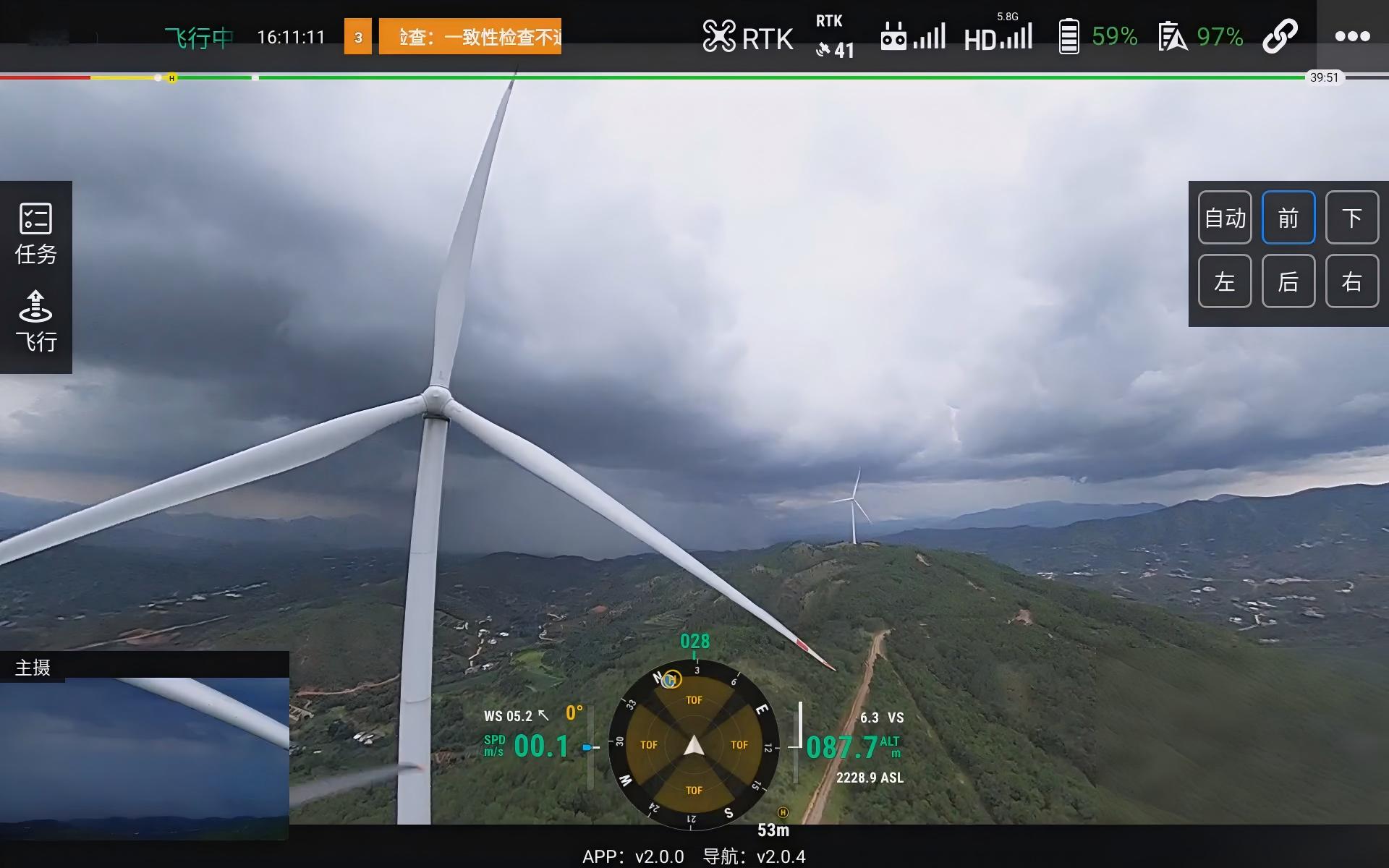
Record the turbine and its parameters, inspected surfaces and deliverables.
Choose the mode with the generation plan in mind and check turbine orientation and safety conditions. Stop and lock the blades before static work.
Plan dynamic missions from parameters. For static missions, generate nine connected inspection segments from the turbine model.
INES executes the route with laser triggering for dynamic capture and waypoint photography for static capture; AGS monitors status and blade distance.
Organize multi-view imagery, use AI to identify suspected anomalies and have specialists review them.
Produce reports and retain history. Static results identify individual blades; dynamic results state that actual blade IDs cannot be reliably assigned.
Organize dynamic results by wind farm, turbine, mission and capture direction, without treating temporary groups as actual blade IDs. Static results link the turbine, specific blade, inspected surface and defect location for blade-level review and historical comparison. Both modes support defect identification, human review and reporting.
Explore the Wind-turbine Inspection Platform ↗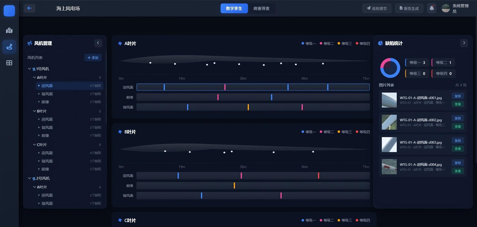
Inspect visible anomalies such as surface cracks, coating loss, corrosion, surface damage and leading-edge erosion. Static inspection adds head-on leading-edge views. AI results require professional review and do not replace final defect assessment.
Retain original images, applicable stitched views, defect review records and reports that state the mode, inspected surfaces and limitations.
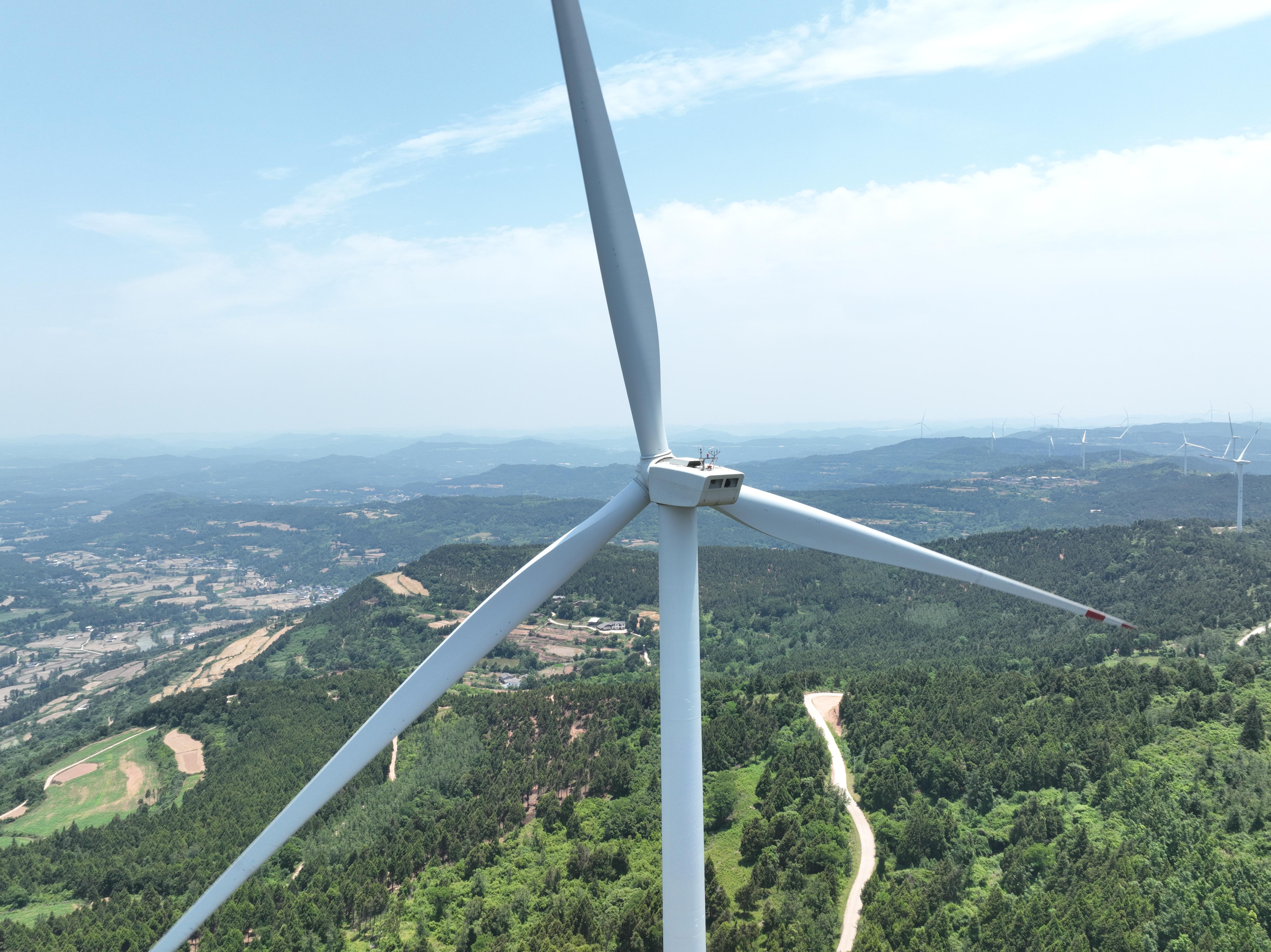
Determine equipment, mission workflow and delivery scope from turbine parameters, site terrain, work organization and result requirements.
Contact a Solution Specialist ↗Last updated