Substructure
Piers, cross beams and pier caps: organize layered and segmented inspection around vertical and transverse components.
 Contact Us ↗
ARP brings 3D bridge models, component annotation, automatic route generation, simulated flight and route stitching into one workspace, helping teams prepare component-based inspection missions for execution.
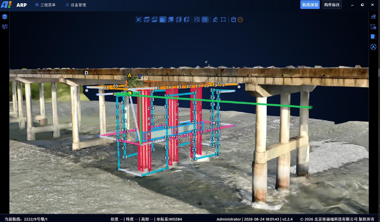
Link components and routes in the 3D model to plan suitable paths for different structures and support later association of imagery and damage with bridge components.
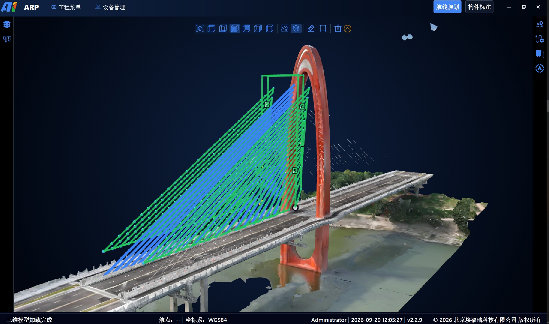
Piers, cross beams and pier caps: organize layered and segmented inspection around vertical and transverse components.
Hollow slabs, small and large box girders, T-girders, arches, towers, stay cables and main cables: plan coverage according to component geometry.
Bridge side faces and parapets: organize continuous acquisition along the bridge while keeping targets linked to route segments.
Plan close-range, multi-view acquisition based on the available space around bearings.
Component annotation is the foundation of route planning in ARP. Specify component types, positions and dimensions on the imported 3D model to create identifiable inspection targets that can be selected for planning.
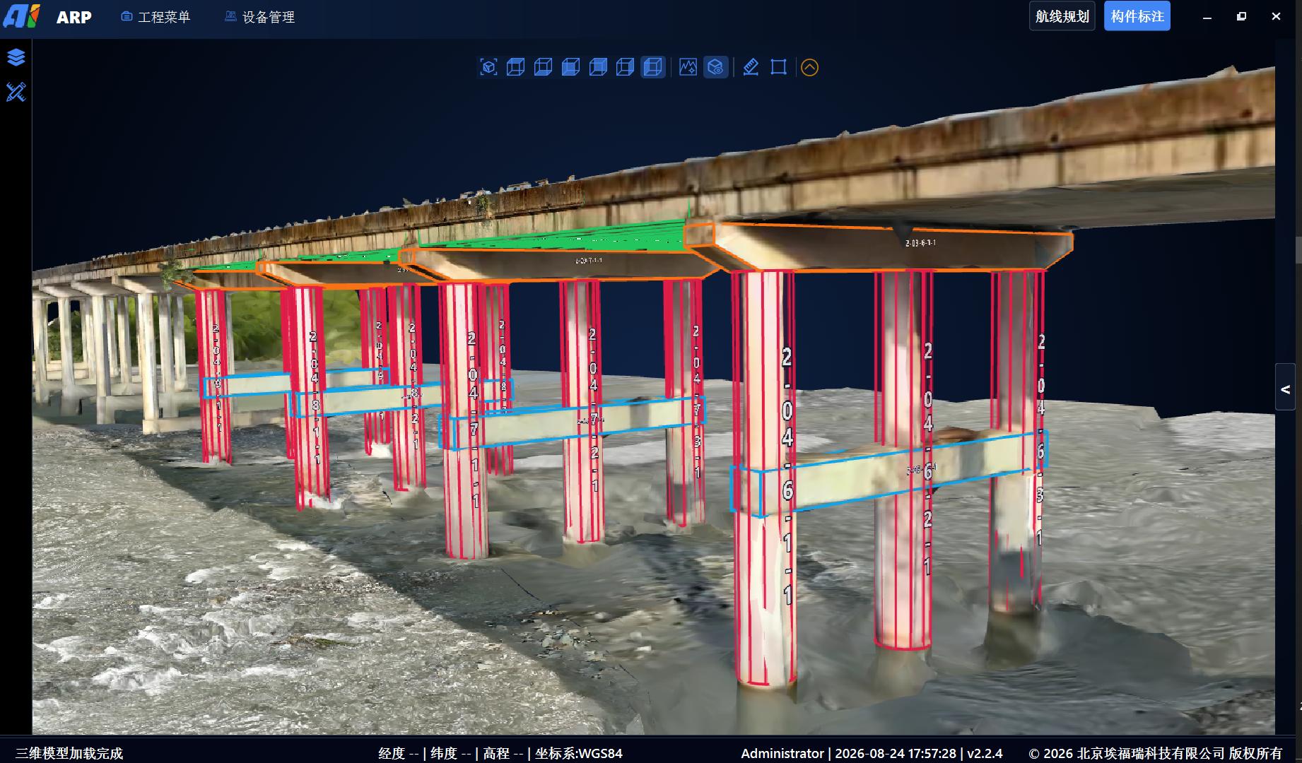
Annotate piers, cross beams, pier caps, girders and bearings, recording their type, position, dimensions and identifier.
Select one or more annotated components and generate routes based on acquisition requirements, reducing point-by-point mission planning.
Component annotations can be exported to the bridge inspection platform through project-specific interfaces, supporting links between imagery, damage and components and subsequent reporting.
Select one or more components, set inspection distance, image overlap and an adapted aircraft model, then let ARP generate waypoints, paths and capture actions. Reduce point-by-point planning while retaining review and adjustment.
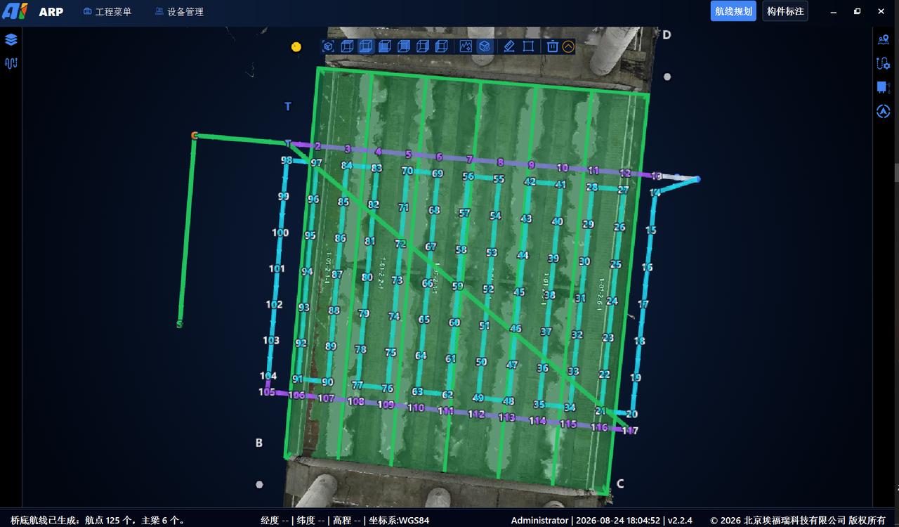
ARP includes a built-in flight simulator. Once a route is planned, simulate the flight around the 3D bridge model without leaving the software to review the flight path, camera directions at waypoints and spatial relationships with bridge components before field operations.
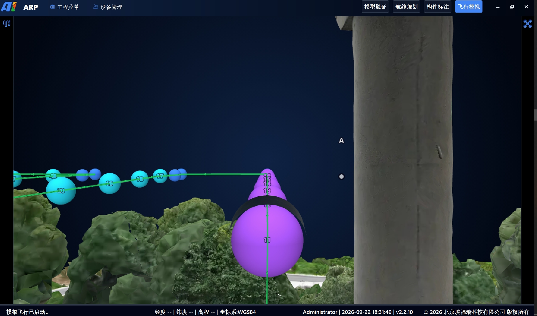
Follow the simulated flight to review nearby components and shooting directions, helping assess coverage, viewing angles and relative distances.
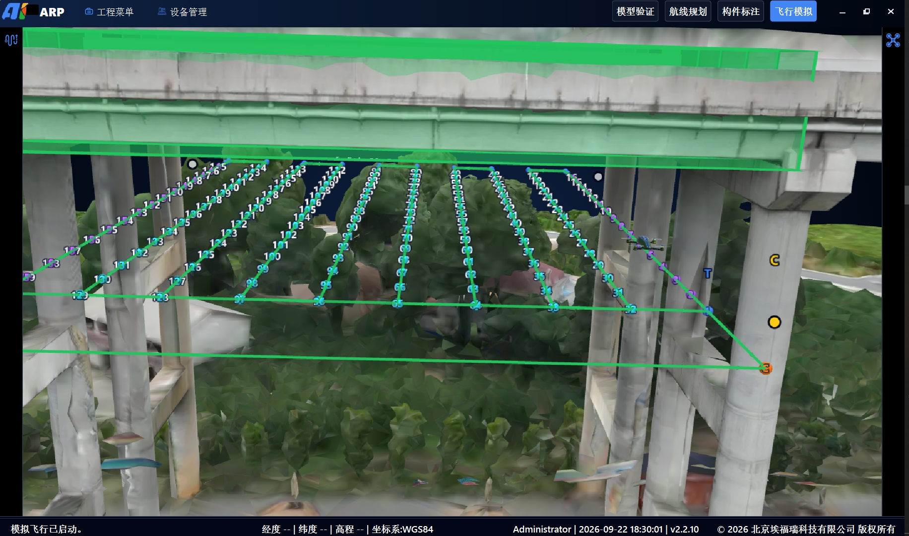
View the route and bridge structure from an external perspective to help identify potential conflicts and explain the planned mission to the team.
Check the model for coverage gaps, incorrect shooting directions and overly close flight segments, then adjust the plan as needed.
Complete model-based checks in advance to reduce the need for replanning on site.
Help pilots become familiar with the route and key waypoints before field operations.
Show the inspection route through simulated flight for joint review by the project team.
Simulation results depend on the imported 3D model and planning parameters. They do not replace site surveys, obstacle checks, risk assessments or real-aircraft validation.
Organize route segments for the same aircraft model into a continuous mission with transitions between segments. Where endurance, payload and site conditions permit, this can reduce repeated takeoffs and mission changes.
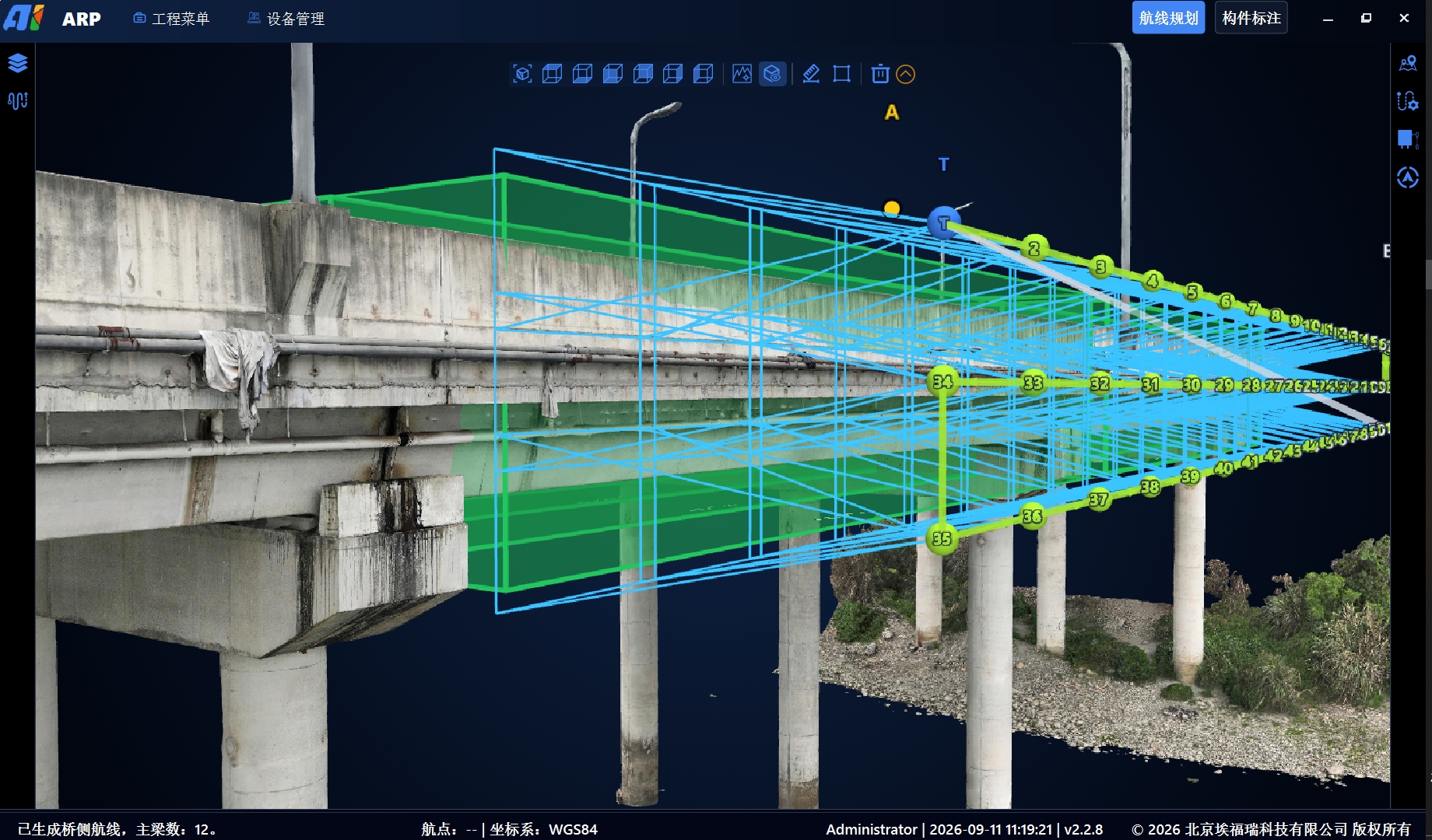
Local missions for piers, girders and bridge sides
Join in work order and review transitions
Inspect multiple areas where operating conditions permit
Review new or changed transitions after stitching. Plan missions around remaining endurance, return requirements and site obstacles; stitching does not imply that an entire bridge can be inspected in one flight.
Organize routes for different aircraft in one project, then review, adjust and export their missions separately. Coordination means shared planning and task allocation, not autonomous formation flight.
Organize missions for larger areas such as bridge undersides and girders according to payload and endurance.
For bearings and spaces between adjacent piers, first verify clearance, aircraft dimensions and accessibility.
Set different shooting directions for complex components to organize consistent acquisition.
Configure supported orientation, photo and video actions so acquisition requirements travel with the route.
With a supported lighting payload, configure illumination for backlit or dim areas.
Generation, simulation, adjustment and stitching can be repeated. Review the mission and confirm field compatibility before export.
ARP delivers planning outputs, onboard and ground systems handle execution and monitoring, and the bridge inspection platform manages components, imagery, damage and reports through project-agreed interfaces.
Plan by component, simulate, review and stitch routes, then export mission files.
Connect positioning, flight control and mission actions to execute routes onboard.
03 / MONITORConfigure missions, monitor status and provide pilot intervention.
04 / MANAGEOrganize imagery, defect review, component association and reports.
KML action support depends on the aircraft, payload and execution software. Component, imagery and damage associations depend on project integration.
Provide bridge type, 3D model, aircraft platform and delivery objectives, and we will help confirm ARP version, interfaces and mission configuration.
Last updated