Dual-Source Positioning Fusion
Combines RTK, LiDAR SLAM and IMU for continuous pose output under changing environmental conditions.
 Contact Us ↗
Combining RTK satellite positioning, LiDAR SLAM and inertial data, INES provides continuous positioning, KML route execution and gimbal-camera coordination for drone inspection across open, under-bridge and confined environments.
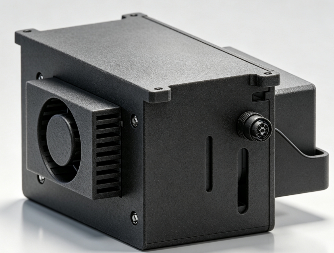
INES connects LiDAR, RTK, IMU, flight control and gimbal cameras, performing positioning fusion, route tracking, mission scheduling and device coordination onboard. It is not a standalone locator, but an onboard control node linking route planning, aircraft execution and inspection acquisition.
Combines RTK, LiDAR SLAM and IMU for continuous pose output under changing environmental conditions.
Parses standard KML missions and executes route tracking and predefined waypoint actions onboard.
Coordinates aircraft attitude, gimbal angle, camera parameters and photo/video actions.
Configures and installs hardware/software according to aircraft, flight controller, LiDAR and payload interfaces.
INES monitors RTK and LiDAR-SLAM quality and uses IMU data for pose continuity. Positioning-source selection and switching must be configured and validated for the environment, map and aircraft.
Provides a centimeter-level position reference in open environments with a valid correction link.
Outputs continuous pose through quality assessment, pose continuity and IMU data.
IMUUses point-cloud maps for positioning in integrated GNSS-denied scenarios.
5–10 cm is a typical LiDAR-SLAM positioning accuracy. Accuracy and stability depend on LiDAR type, map quality, structural features, flight speed, installation calibration and environmental conditions.
Waypoints and actions are planned in ARP and exported as KML, then dispatched to INES through AGS or another mission entry point. The onboard engine parses, validates and executes route tracking, yaw modes and ordered actions.
One-touch mission execution does not remove operator supervision. Takeoff, return, exception handling and manual takeover must comply with aircraft, airspace, site safety rules and project manuals.
Tracks the route in waypoint order and dwells at designated positions.
Adjusts aircraft heading and gimbal pitch/roll as defined by the mission.
Configures exposure, focal length, resolution and other parameters for integrated payloads and interfaces.
Supports single, hover and distance-interval photos plus timed or continuous video.
For integrated gimbal cameras, INES controls photography, video, gimbal angle and selected camera parameters through waypoint actions.
Combines aircraft yaw with gimbal pitch and roll to adjust target viewing direction.
Executes single, hover or distance-interval photos and timed or continuous video as defined.
Configures exposure, focal length, resolution and other imaging parameters supported by the payload interface.
Reuses route and action configurations to provide a consistent basis for longitudinal data comparison.
INES records waypoint indices, executed actions and mission status, supporting resume, selected-waypoint start and segmented execution for battery changes, reshoots and focused reinspection.
The module reference dimensions are approximately 10 × 7 × 5 cm and its weight is approximately 250 g. LiDAR, interface adapters, cooling and mounting structures cause slight variation across aircraft integrations.
DJI PSDK, PX4 and different aircraft and LiDAR platforms can be integrated by project; actual support depends on interface versions, firmware and system commissioning.
Integrated according to payload, power, payload interface, flight-control protocol and mechanical installation.
Different LiDARs can be combined with RTK and IMU for positioning input, with the configuration defined by project.
Gimbal angle, imaging and parameter-control scope are determined by the payload SDK and control interface.
ARP plans waypoints and actions and outputs KML; AGS dispatches missions, monitors status and supports manual intervention.
As the onboard execution node in three industry workflows, INES connects dedicated mission software and result processes for bridge components, wind-turbine blades and confined spaces.
For piers, bridge undersides, bearings and other components, this workflow connects component-level route planning, continuous under-bridge positioning, field monitoring and defect-result management.
Connect positioning, flight control and mission actions to execute routes onboard.
For wind-turbine blade inspection, this workflow organizes missions by turbine and blade parameters and connects onboard execution, dynamic monitoring, blade-level result organization and defect review.
Coordinate onboard generation and execution of an inspection mission adapted to the current turbine.
For GNSS-denied tunnels, industrial plants, culverts and enclosed warehouses, this workflow connects point-cloud route planning, onboard positioning and execution, field monitoring and result delivery.
Maintain positioning against the point-cloud map and execute the mission onboard.
Organize inspection data, anomaly review and deliverables by project.
Different scenarios require different positioning sources, map preparation, sensing configurations and safety strategies and must be validated separately.
Bridges different satellite-signal conditions above and below the deck for close-range missions.
INDOORExecutes planned routes in tunnels, plants and similar environments using LiDAR-SLAM maps.
WINDOrganizes blade acquisition using integrated aircraft, positioning and gimbal-camera actions.
Provides project-specific positioning and mission configuration for equipment rooms, warehouses and energy facilities.
Provide aircraft model, sensor configuration, operating space and mission requirements, and we will help confirm the INES version and integration plan.