LiDAR and Vision Fusion
Uses one LiDAR and two cameras as the front-end multimodal sensing configuration.
 Contact Us ↗
One LiDAR and two cameras are integrated in a sealed enclosure to provide front-end multimodal data for intelligent train obstacle detection and engineering-vehicle protection.
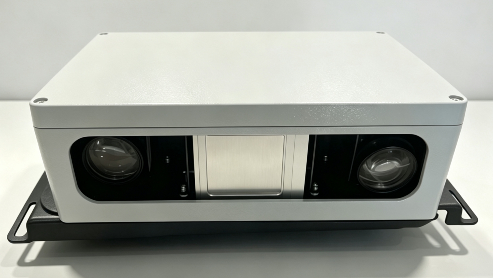
Sensor-L uses one LiDAR and two cameras to synchronously capture spatial-ranging and image data ahead of the vehicle and around the track, supporting target recognition, distance assessment and result review.
Uses one LiDAR and two cameras as the front-end multimodal sensing configuration.
Serves as shared front-end hardware for TIDS and EV-IPS, with installation position and application software configured by project.
Two cameras synchronously capture external-environment imagery for target recognition and result review.
IP66 protection, wide-temperature operation and stainless-steel mounting hardware support exterior rail-vehicle deployment.
The website presents only the user-facing sensing configuration; calibration, algorithms and data processing are completed for each TIDS or EV-IPS project.
Provides environmental ranging data for target and trackside perception.
Acquires images through two vision channels for recognition and review.
The shared element is the front-end hardware platform. Quantity, orientation, detection coverage, host interfaces and software functions are determined separately for each TIDS or EV-IPS project.
Provides data from one LiDAR and two cameras for forward train-environment perception.
View Solutions ↗Functions as the front-end unit for engineering-vehicle surroundings perception, with layout and orientation determined by vehicle type and operating scenario.
View Solutions ↗Sensor-L provides spatial-ranging and image data to TIDS or EV-IPS; recognition, assessment and application output are completed by the corresponding system.
The LiDAR captures spatial-distance information for targets and the surrounding rail environment.
Two cameras synchronously capture external-environment images for visual recognition.
LiDAR and visual data are calibrated, associated and analyzed in the corresponding system.
Target detection, distance assessment and prompts are produced according to TIDS or EV-IPS project requirements.
The enclosure measures 340 × 235 × 120 mm, excluding mounting sheet metal, and is secured by a bent 304 stainless-steel bracket. The installation drawing should reserve additional space for the bracket and cable direction.
Final hole positions, fasteners, grounding, field-of-view obstruction and cable bend radius must be confirmed against the vehicle and field installation drawings.
The following parameters are based on the current V1.0 datasheet and may be used for preliminary design and installation coordination. Formal supply configuration and acceptance criteria are subject to project technical documents.
Sealed protection, wide-temperature operation, waterproof connectors and vehicle-body grounding together define the environmental integration boundary.
The datasheet states that the product meets EN 50155 requirements. Certification status, applicable version, installation conditions and scope are subject to formal certification documents and project requirements.
Confirm the TIDS or EV-IPS application, mounting direction, target area, obstruction conditions and detection-range requirements.
Confirm brackets, hole positions, grounding, waterproofing, cable routing and connector maintenance clearance.
Complete LiDAR and vision calibration, network configuration and communication with the corresponding system host.
Validate field-of-view coverage, data quality, environmental adaptability and system functions under project conditions.
Provide the vehicle type, installation space, viewing direction and system-interface conditions, and we will help confirm the Sensor Box configuration and layout.
Last updated