AFR-IPS-VC-V200 · ENGINEERING VEHICLE PROTECTION

EV-IPS Onboard Computer

Coordinate Environmental Perception, Vehicle Signals and Protection Functions Onboard

For rail engineering-vehicle protection systems, it receives surrounding-perception data, vehicle I/O and speed information, performs onboard intelligent analysis and business processing, and supports driver prompts and project-defined vehicle integration.

Multi-Source Sensor AccessUnified Onboard Data ProcessingVehicle Interface CoordinationConnect Engineering-Vehicle SystemsRail-Environment AdaptationDesigned for Onboard Deployment
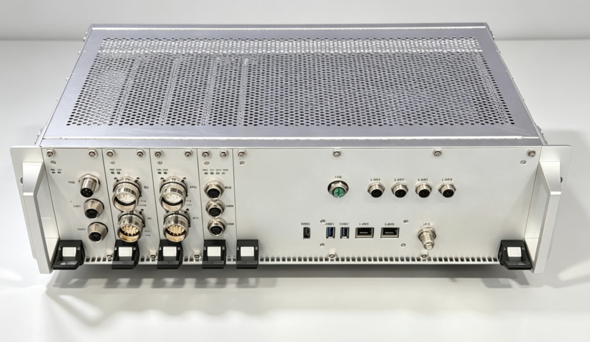
AFR-IPS-VC-V200 EV-IPS Onboard Computer实物正面
AFR-IPS-VC-V200Standard 19-inch 3U Chassis · Product Photo
PRODUCT POSITIONING

More than Algorithm Computing: Connecting Vehicle Status and Execution Boundaries

AFR-IPS-VC-V200 combines sensor networks, vehicle digital and analog signals, speed sensors, GPS, serial communication and commissioning interfaces in one host for surrounding-target perception, risk analysis and information coordination.

01

Onboard Intelligent Computing

Runs environmental perception, business analysis and protection-system software locally on the engineering vehicle.

02

Vehicle-Signal Coordination

Connects project-defined vehicle-status and business signals through DI, DO and 0–20 mA analog interfaces.

03

Multi-Source Spatiotemporal Data

Supports speed sensors, PWM, GPS, network and serial data inputs.

04

Rail-Environment Adaptation

Configured for DC 110 V power, 19-inch cabinets and rail-vehicle environmental requirements.

SYSTEM ROLE

Two Input Domains Feed Onboard Computing to Output Protection Information within Project Boundaries

Environmental-perception data and vehicle status enter one computing platform, which processes them and outputs project-defined information to the DMI or vehicle interfaces.

INPUT A

Environmental Perception

  • Project Sensors such as Cameras / LiDAR
  • 10G and Gigabit Networks
  • Serial Communication
INPUT B

Vehicle Status

  • Digital DI / DO
  • 0–20 mA Analog Signals
  • Speed Sensor / PWM / GPS
COMPUTE

Fusion and Analysis

  • Onboard Data Organization
  • Intelligent Perception Algorithms
  • Project Business Logic
OUTPUT

Information Coordination

  • DMI Driver Information
  • Status and Warning Output
  • Vehicle Integration as Project-Defined

Vehicle integration must be designed around vehicle interfaces, safety analysis and project authorization. The presence of hardware outputs does not mean direct vehicle control is performed in every project.

INTERFACE ARCHITECTURE

Connections from High-Speed Perception Networks to Vehicle Hardwires

Interface capabilities are based on the V2.0 datasheet. Connector pinout, signal definitions, isolation and protection are subject to the project interface-control document.

NET

High-Speed Network

  • 1 × M12 X-Code female, 10G
  • 4 × M12 A-Code male, 1000M
  • For project sensors and system network
VEHICLE

Vehicle Digital I/O

  • One set of 8 DI / 8 DO
  • One set of 4 DI / 4 DO
  • M23 male/female connectors
ANALOG

Analog Signals and Speed

  • 6 × 0–20 mA inputs
  • 2 × 0–20 mA outputs
  • Speed sensor and 4 × PWM
SERVICE

Communication and Maintenance

  • RS485 / RS232
  • HDMI / 2 × USB / 2 × RJ45
  • TNC-K GPS antenna interface
VEHICLE I/O

Connect Vehicle Status and Speed Data with Protection Functions

In addition to the sensor network, the host provides digital, analog, speed-sensor, PWM and GPS interfaces so protection functions can incorporate engineering-vehicle operating status.

12 DITotal Digital Inputs across Two Vehicle Interfaces
12 DOTotal Digital Outputs across Two Vehicle Interfaces
6 IN / 2 OUT0–20 mA Analog Interfaces
4 × PWMSpeed-Related Signal Inputs
Vehicle StatusSpeed / GPSEnvironmental PerceptionAFR-IPS-VC-V200Analysis and Information CoordinationSignal use and integration logic are project-defined
POWER & INSTALLATION

Designed for DC 110 V Supply and Standard Cabinet Installation

The host supports DC 77–135 V input, with DC 110 V recommended, and provides two DC 24 V outputs. It uses a 19-inch 3U chassis with a depth of 315 mm.

482.6 mmWidth132.6 mmHeight315 mmDepth9.6 kgDevice Weight
19″ / 3U
482.6 mmEV-IPSApprox. 150 mm front clearance recommended for cabling and maintenance
315 mm
TECHNICAL SPECIFICATIONS

AFR-IPS-VC-V200 Key Specifications

The following content is based on the current V2.0 datasheet for preliminary selection. Formal supply configuration, acceptance criteria and interface definitions are subject to project technical documents.

System Power

Input Voltage
DC 77–135 V; DC 110 V recommended
Power Interface
1 × M12 S-Code male, DC 110 V input
Auxiliary Output
2 × M12 female, DC 24 V output
Maximum Design Power
200 W

Mechanical and Environmental

Mechanical Dimensions
482.6 × 132.6 × 315 mm
Device Weight
9.6 kg
Mounting
Secured by 4 × M6 bolts
Operating Temperature
-25 ℃–+70 ℃
Operating Humidity
10%–90%, non-condensing
ENVIRONMENTAL ADAPTATION

Define Product Applicability for Engineering-Vehicle Environments

Temperature/humidity, shock/vibration and EMC ratings provide baseline boundaries for selection and project validation.

-25 ℃–+70 ℃Operating Temperature
10%–90%Operating humidity, non-condensing
Class 1BDatasheet states compliance with EN 61373:2010 shock and vibration requirements
EN 50155:2017EMC requirements stated in the datasheet

The datasheet states EN 50155 compliance. Certificate status, applicable version, configuration scope and project standards are subject to formal certification and contract technical documents.

PROJECT INTEGRATION

Integrate the Vehicle from Signal List through System Commissioning

01

Vehicle and Mission Confirmation

Confirm vehicle type, operating mode, sensor configuration, speed source, driver interaction and protection-function boundaries.

02

Interface and Installation Design

Confirm network bandwidth, DI/DO, analog signals, connector pinout, power protection, cabinet and cable space.

03

Software Deployment and Commissioning

Deploy project software and commission data and status with sensors, DMI and vehicle systems.

04

Validation and Delivery

Perform functional, performance, interface, environmental and vehicle-level validation under project requirements.

CONFIGURE FOR YOUR ENGINEERING VEHICLE

Deploy the Computing Platform with Vehicle, Signal Interfaces and Protection Strategy

Provide vehicle power, signal list, sensor configuration and operating scenario, and we will help confirm hardware configuration and integration boundaries.

Contact the Product Team