Help reduce operational risk
Combine obstacle, signal, speed-limit and work-boundary information to support alerts and protection against collisions, unauthorized movements and overspeed.
 Contact Us ↗
EV-IPS provides onboard perception, risk alerts and protection support for engineering vehicle operations and metro or urban rail passenger train trials where signalling protection is not yet available.
Turn operating risks in engineering work and passenger train trials into clear alerts for timely driver decisions and response.
Combine obstacle, signal, speed-limit and work-boundary information to support alerts and protection against collisions, unauthorized movements and overspeed.
Present targets ahead and vehicle status together to help drivers focus on relevant information during engineering work or passenger train trials.
Configure the system for vehicle types, line conditions and interfaces to integrate protection with engineering or trial procedures.
Configure EV-IPS for engineering operations or passenger train trials according to the vehicle type, operating phase and available protection.
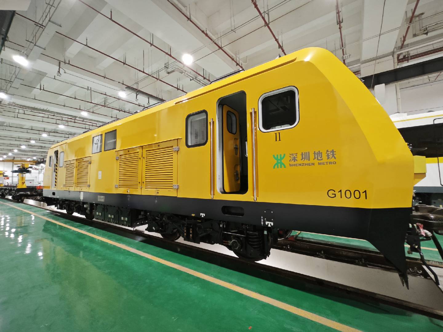
Monitor obstacles ahead, signals, speed limits and work-zone boundaries during engineering vehicle movements and work.
Explore engineering vehicle applications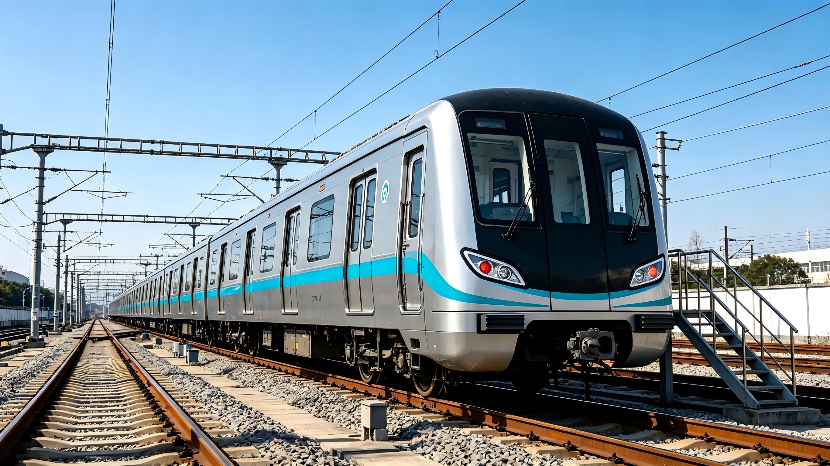
Provide independent onboard assistance for passenger trains during trials where signalling protection is not yet available.
Explore passenger train trialsDuring trials where signalling protection is not yet available, EV-IPS is installed on the passenger train under test—not on an engineering vehicle—to provide independent onboard assistance with targets ahead, speed limits and work-zone boundaries.
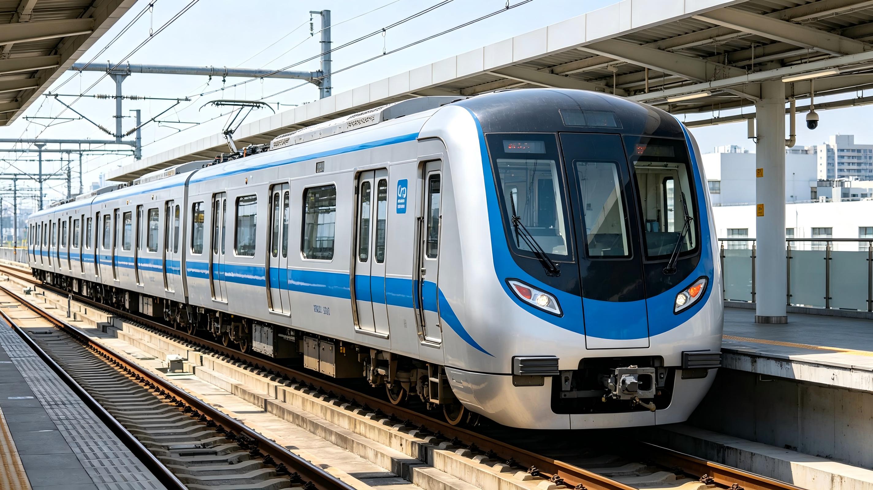
For delivery-stage line trials, sensors, a controller and a cab HMI installed on the passenger train help drivers assess signals, obstacles and operating boundaries.
For test runs after line upgrades or major overhauls, speed restrictions, work-zone boundaries and targets ahead help identify overspeed, overrun and collision risks.
No modification to existing signalling is required. Autonomous operation can work without ground signalling or route inputs, with a simplified digital map supporting operation across lines.
Positioning across tunnels, depots and open-air sections supports protection against signal overruns, work-zone incursions, overspeed and track obstacles.
Recommended speed profiles and brake notches, together with upcoming platform, interstation distance and estimated arrival information, help drivers monitor trial operations.
Assistance does not replace trial management, driver observation or established safety procedures. Vehicle interfaces, control strategies and operating scope require project-specific validation.
Metro engineering vehicles perform shunting, construction, maintenance and rescue alongside other work. EV-IPS not only detects targets; it combines real-time perception with vehicle position, speed, line limits and work tasks to provide understandable, actionable safety prompts.
For cross-line operation, independent onboard protection and positioning in complex environments, EV-IPS uses configurable engineering options to adapt to different line conditions and operating modes.
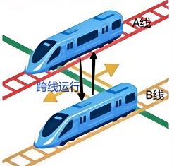
Simplified digital maps support cross-line operation and efficient deployment of vehicle protection, balancing operational flexibility with setup efficiency.
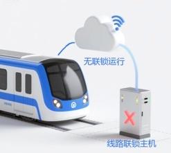
Supports operation without ground route-information input, independently recognizes signals ahead and coordinates driving protection; driver operation and intervention remain available when an abnormal condition occurs.
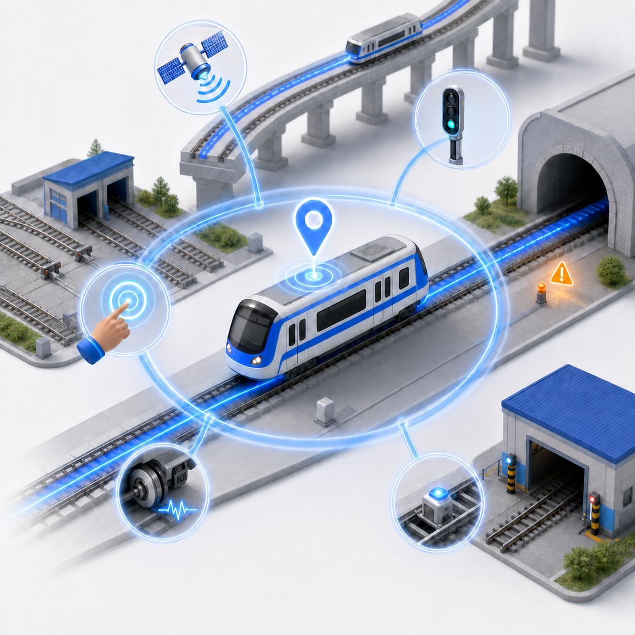
Fuses RTK, lineside signals, track beacons and driver-forced calibration to support surface, elevated, underground, depot and garage environments, including positioning initialization, in-operation positioning continuity and abnormal-positioning alerts.
Workers, vehicles, buffer stops, grounding rods, cables and tools may intrude into the vehicle's operating clearance.
During cross-line work, restricted visibility or operation without interlocking data, drivers face greater recognition and decision pressure.
Possession work requires clear boundaries to prevent vehicles leaving the designated section and affecting other operations.
Permanent and temporary speed limits, work mode and targets ahead jointly determine safe operating speed.
From risk detection and safe-speed-curve generation to driver warnings and vehicle protection, all four capabilities share the same perception, positioning and computing foundation.
Recognize track geometry, establish a 3D operating clearance, and fuse vision with point clouds to identify intrusions affecting safety.
Combine electronic maps, vehicle position and visual signal recognition to create prompts, protection endpoints and speed curves for mainline red and depot blue signals.
The driver sets work-section boundaries on the HMI; the system creates a protected range and prompts or intervenes as the vehicle approaches it.
Permanent, temporary and work speed limits, signal state and obstacle distance combine into warning, service-braking and emergency-braking strategies.
Depending on project conditions, the system can use fully onboard active perception or connect to interlocking, wireless communications, RTK or wayside beacons for enhanced route and positioning information.
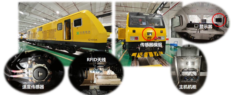
Industrial cameras and LiDAR capture images, point clouds and track-environment information ahead.
Fuse speed sensors, inertial data, RFID and electronic maps to continuously update vehicle position and speed.
Performs multi-source processing, target recognition, risk assessment, protection-curve calculation and event recording.
Displays speed, limits, signals, obstacles, route and system status, with voice prompts and mission configuration.
Outputs alerts and coordinates with service braking, emergency braking or traction inhibit according to project interfaces.
The system selects the appropriate front or rear sensing unit from the active cab and fuses positioning, speed, electronic-map and vehicle-state data for risk calculation.
Obstacle, signal and environmental-feature perception
Open-air and underground fused positioning
Vehicle speed and direction calculation
Active cab, controller status and line information
Multi-source Fusion · Vehicle Positioning · Target Recognition
Safe-speed Curve · Risk Assessment · Event Recording
Visual and voice warnings, mission configuration
Vehicle protection coordinated to project conditions
Synchronize system status and required data as needed
Typical system architecture. Equipment quantity, interface scope, installation and coordination strategy depend on vehicle type, line conditions and project safety boundaries.
Choose vehicle-infrastructure coordination or locomotive autonomous perception according to existing line systems, operating mode and retrofit scope.
Connect to interlocking and route data, using vehicle-ground communications to feed signal, route and operating information into protection decisions.
Independent protection based on onboard perception, electronic maps, positioning and speed measurement without relying on ground interlocking interfaces.
The system recognizes track geometry and maps visual targets and LiDAR points into the vehicle clearance. Only targets relevant to the current route and safety boundary proceed to distance, speed-curve and protection calculations.
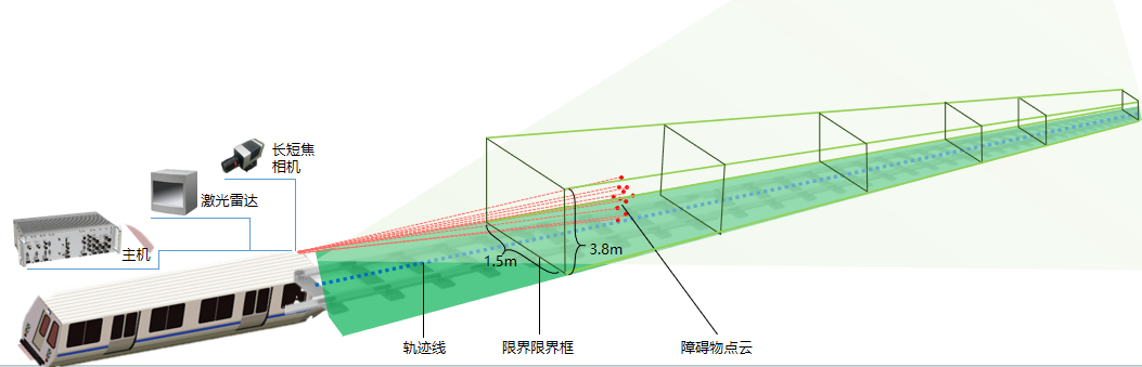
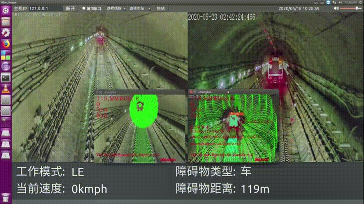
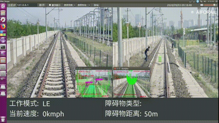
Front and rear sensors capture vision and LiDAR data in real time to recognize track, signals and targets ahead.
Combine vehicle speed, position, electronic map, work route and boundary settings in the current operating scenario.
Dynamically generate prompt, control and protection curves from target distance, line restrictions and braking parameters.
The HMI provides visual and voice prompts; when project-defined conditions are met, corresponding protection is applied through vehicle interfaces.
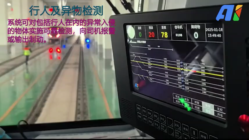
The HMI displays vehicle speed, current limit, target distance, signal state, obstacle count, route and speed curve, with visual and voice prompts supporting driver judgment.
Straight-track conditions
400×1500 mm, straight-track conditions
Red, yellow, green, blue and white aspects
Using RTK and related positioning data
Fusing environmental features and other positioning data
Documented System Specifications
Detection and positioning depend on target size, line curvature, weather, lighting, positioning conditions, installation and vehicle speed. Final values are subject to project specifications, field tests and acceptance criteria.
The following are typical documented configurations; interfaces, power and mounting must be adapted to the vehicle.
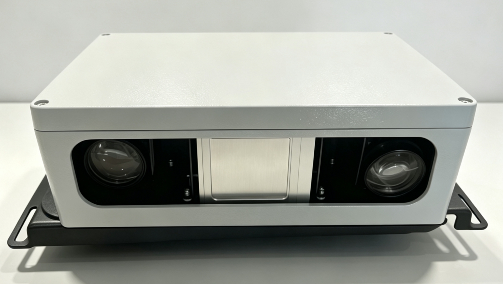
One lidar and two cameras provide perception data for intelligent vehicle protection.
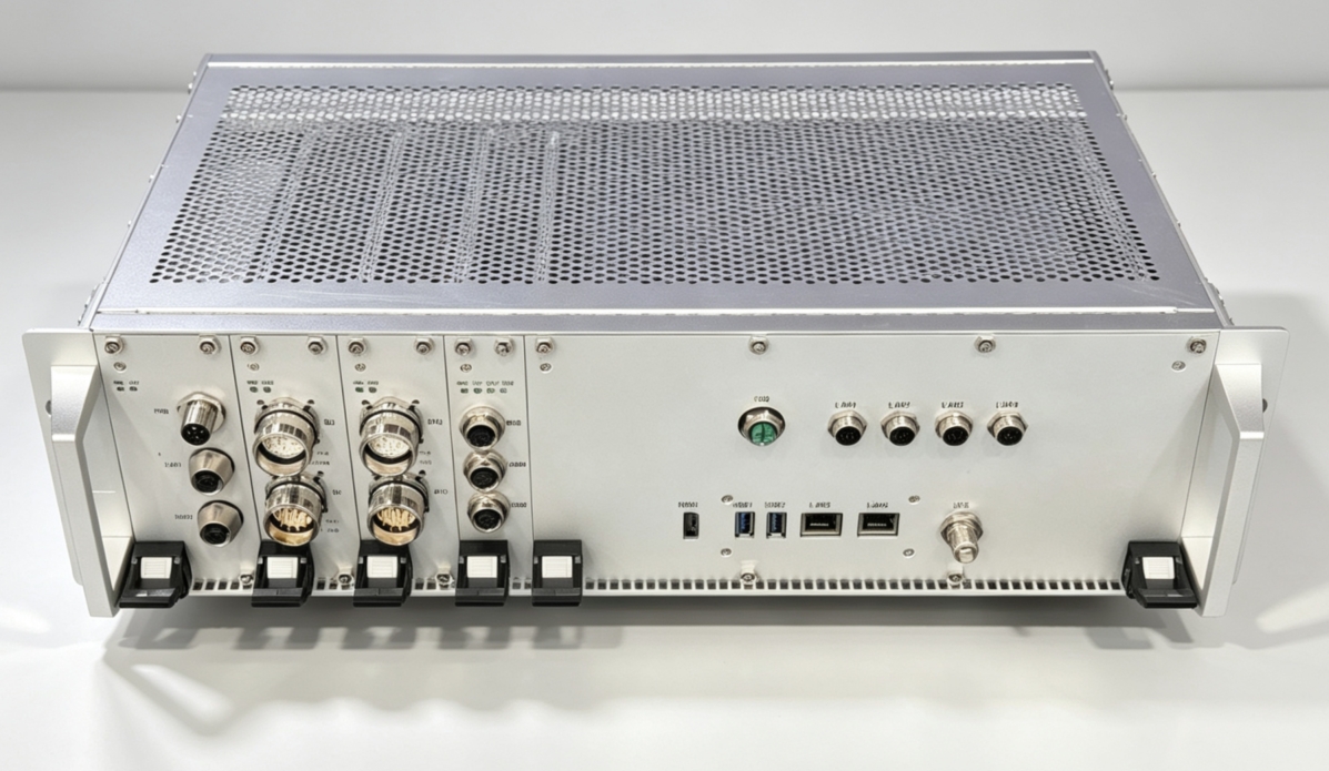
An onboard processing platform for multi-source perception, intelligent recognition and protection decisions.
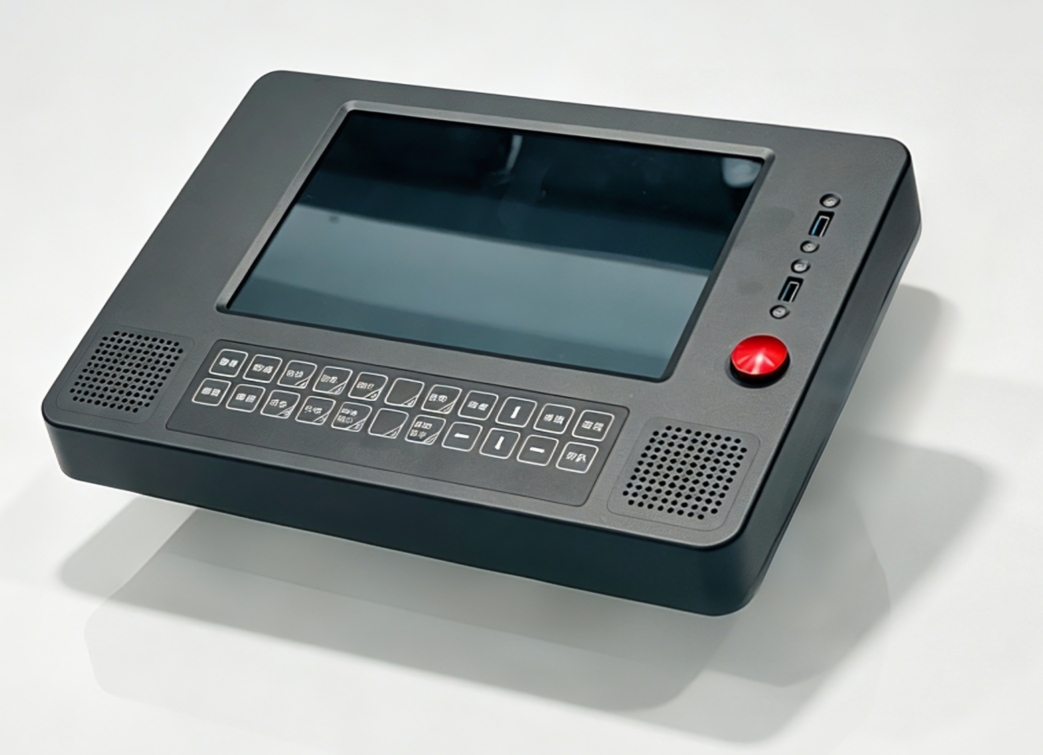
An integrated terminal for operating status, protection curves, voice alerts and mission configuration.
The latest case adds Foshan Metro Line 2 testing. Field practice across vehicles, line systems and work environments continually validates installation, perception and operating workflows.
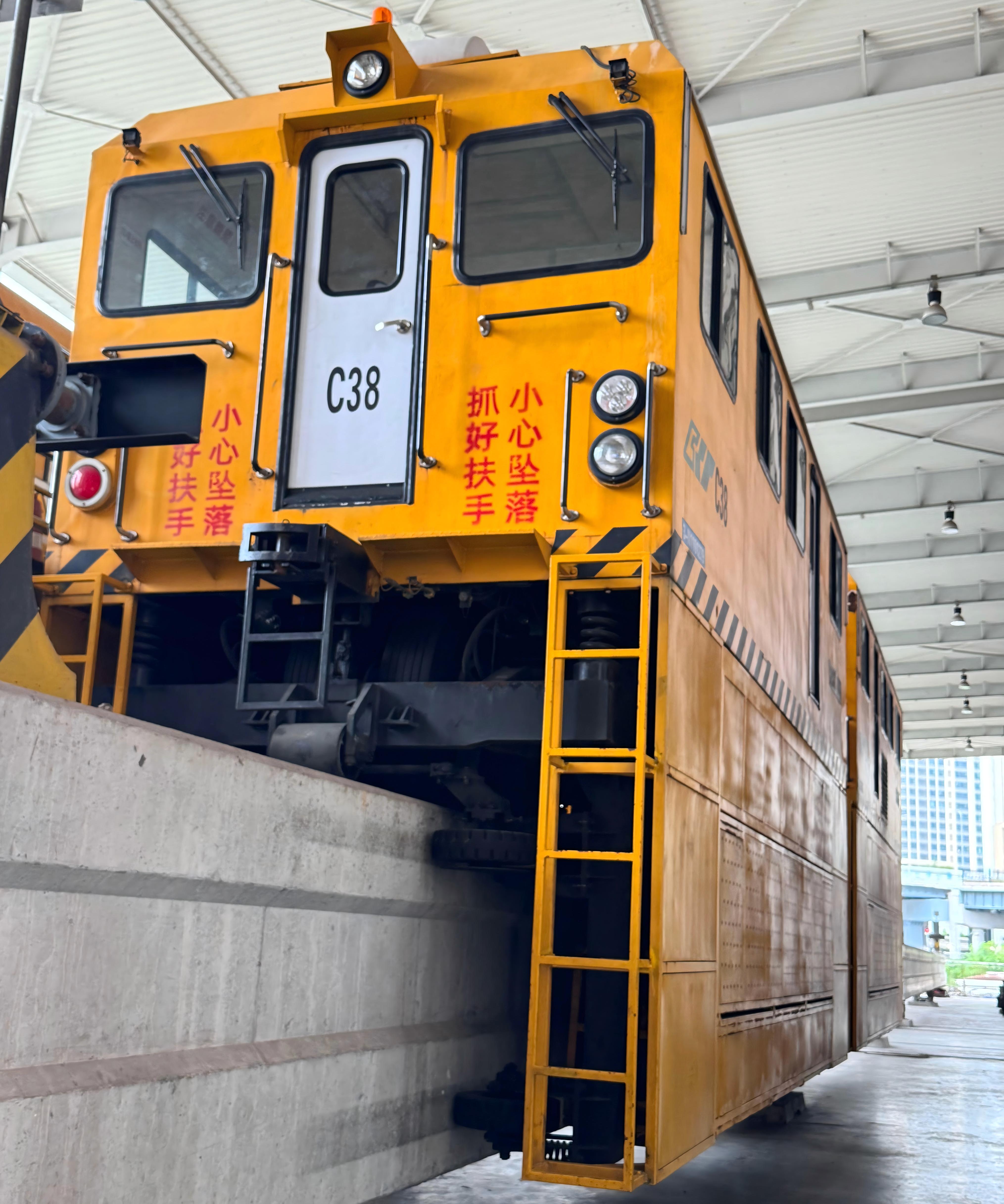
Onboard perception and intelligent protection support for the movement and work operations of new-energy straddle-beam monorail engineering vehicles.
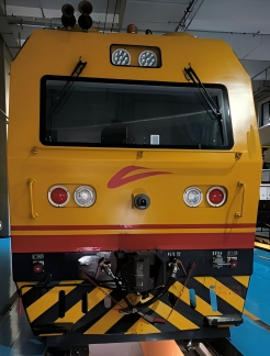
Line-wide testing of HD-map positioning, overspeed protection and detection of small obstacles, pedestrians, buffer stops, grounding rods, trains and signals.
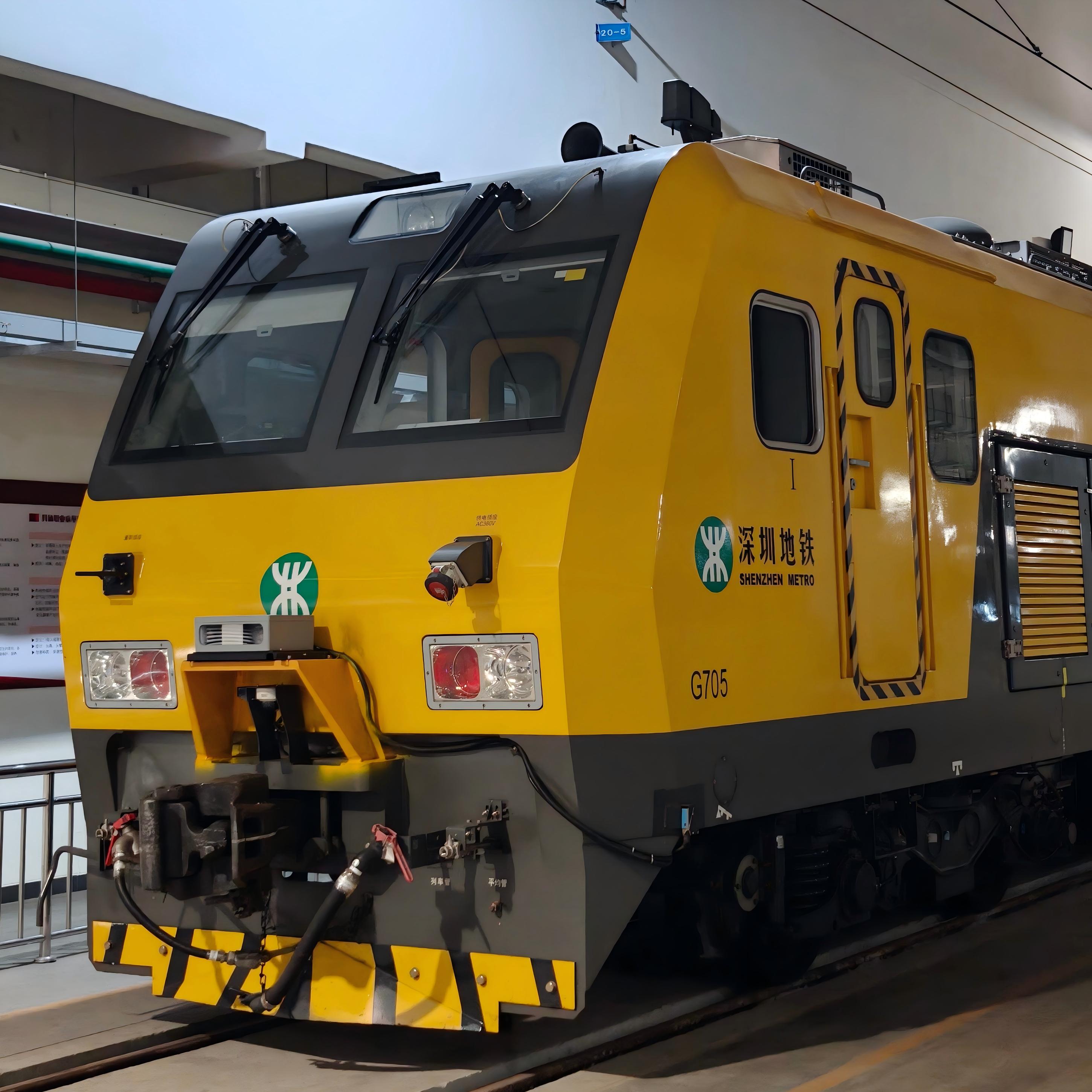
Line tests and engineering validation of intelligent safety protection for mainline and depot engineering vehicles.
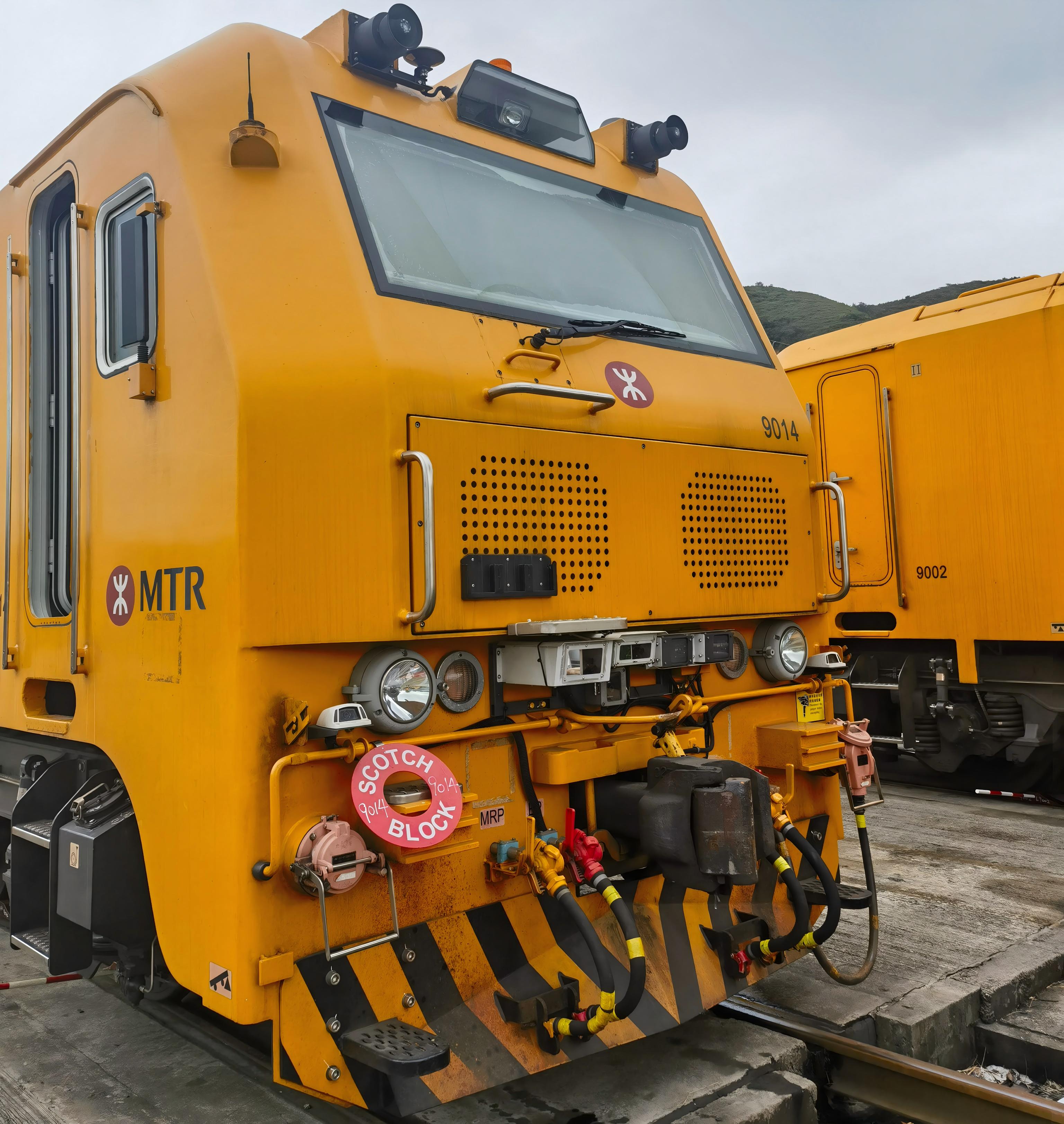
For manual driving inside work zones, detect trains, pedestrians, grounding rods and red boundary beacons to provide active perception assistance.
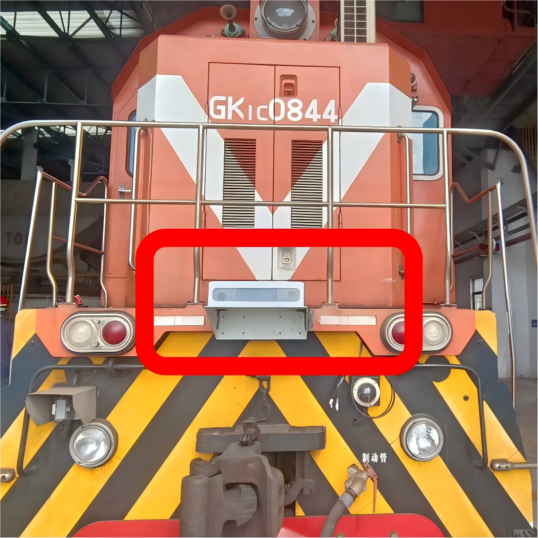
Validate onboard perception in industrial rail shunting and transport environments.
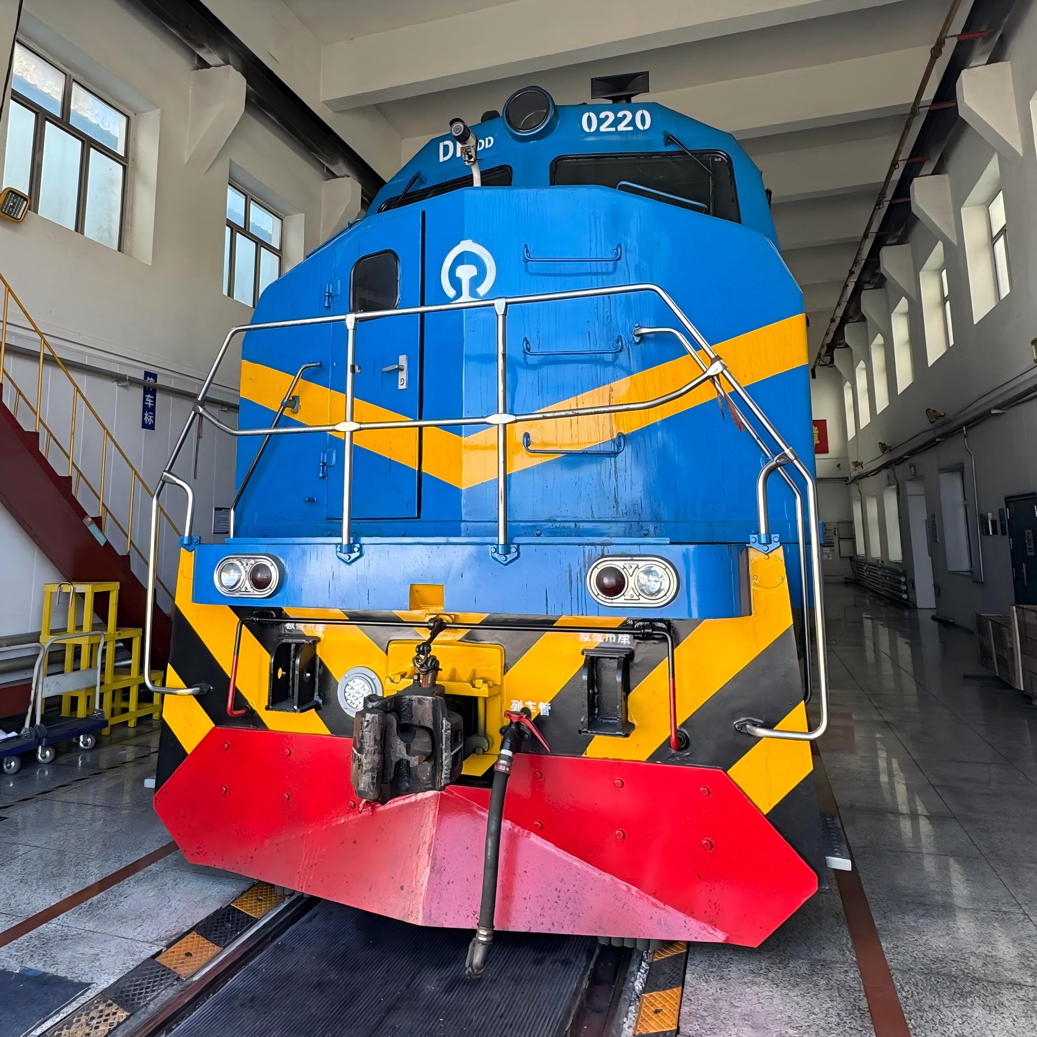
Field deployment of forward perception and safety protection for locomotives in a mining environment.
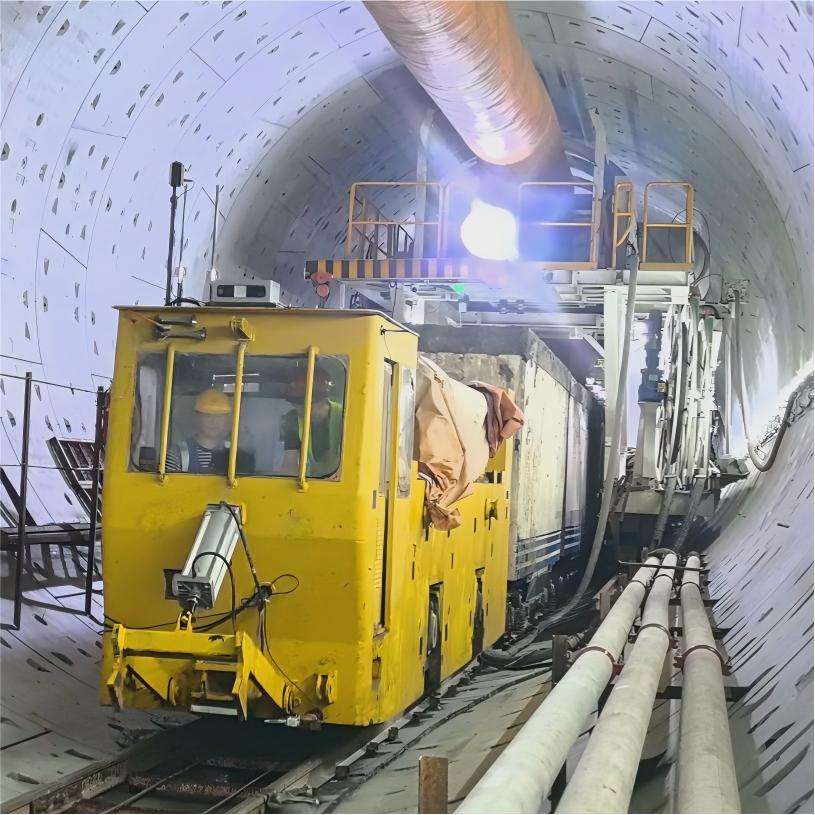
Forward perception and intelligent protection support for transport vehicles handling horizontal logistics in tunnels during shield construction.
From site survey and vehicle adaptation to line testing and delivery, define perception coverage, system boundaries and acceptance conditions.
Last updated