Follow the mission through GNSS-denied spaces and slippery ground
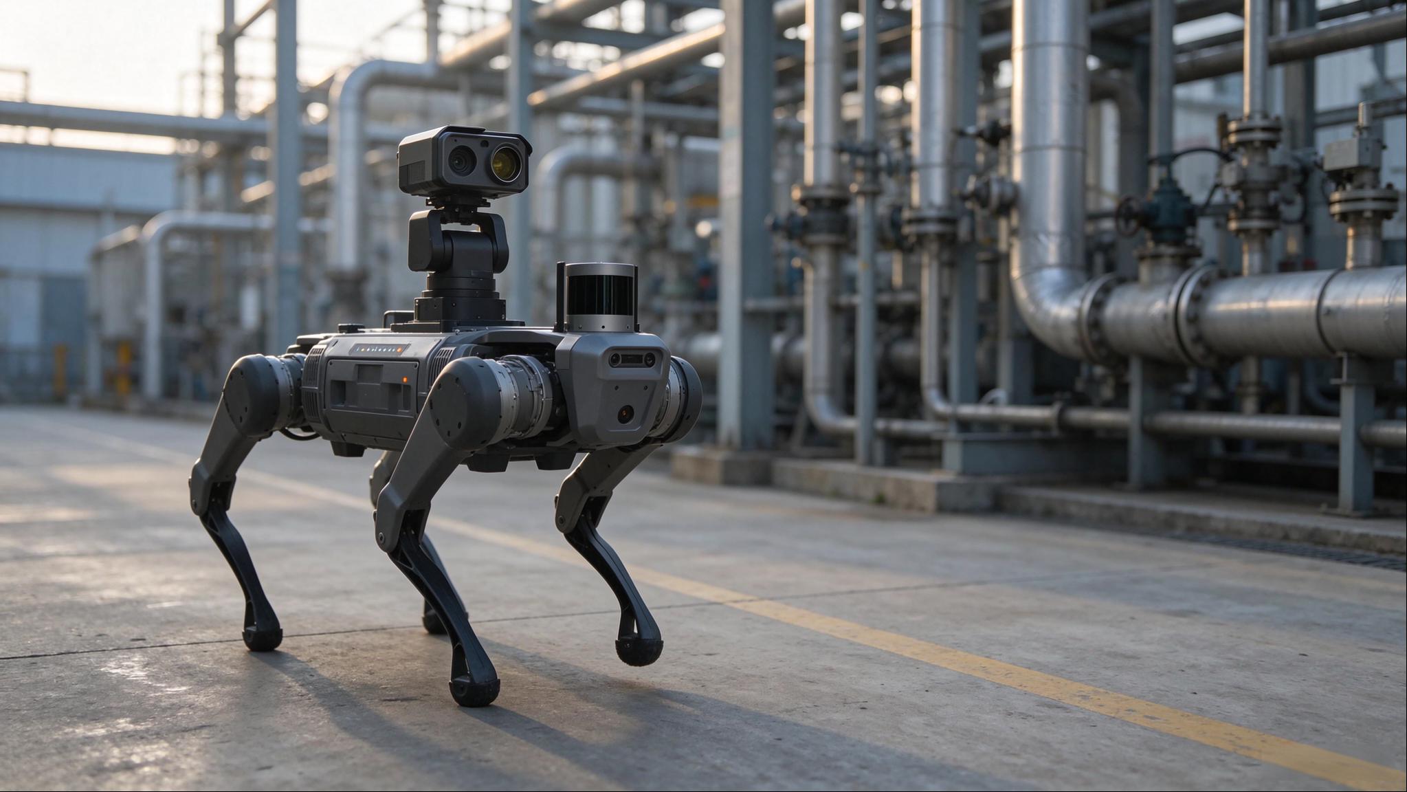
For close-to-ground inspection of utility tunnels, operational and construction tunnels, equipment and electrical rooms, and outdoor yards, an INES-equipped quadruped follows ARP mission files, captures visible-light, thermal and point-cloud data at inspection points, and sends the data to an inspection platform for intrusion, meter-reading, anomaly and deterioration analysis.
RTK / LASER SLAM SWITCHINGMULTI-SENSOR FUSIONMISSION FILE DECOUPLEDAI INSPECTION
CUSTOMER VALUE
Customer Value Summary
Turn close-to-ground inspection and repeated close checks into reusable, comparable missions.
01
Bring ground-level views into routine inspection
Drones cover upper structures, while equipment backs, cabinet interiors, utility-tunnel floors and tunnel inverts still need close access. A ground platform records these areas from a stable viewpoint, reducing repeated bending, lighting and point-by-point approach by personnel.
02
Make each inspection a reusable mission
Map, mark points and plan once, then export a mission file. Subsequent operations can recall a prepared mission without repeating onsite teaching; switch routes by switching files.
03
Connect capture directly to analysis
Visible-light, thermal and point-cloud data upload by category for intrusion, meter-reading, anomaly and deterioration analysis, rather than remaining a batch of photos awaiting manual organisation.
01 · OPERATIONAL BARRIERS
Four constraints in ground inspection
The challenge is not simply whether the robot can walk, but whether its position and captured data remain reliable.
01
Positioning breaks between environments
RTK works outdoors, but satellite reception can disappear in tunnels and equipment rooms. A single positioning mode cannot cover mixed environments; pose jumps during switching can shift the route.
02
Real floors are not ideal surfaces
Oil, standing water, metal grating and polished floors can cause a quadruped's feet to slip, affecting body stability and motion estimation and making positioning and route tracking more difficult.
03
Planning is tied to field execution
Onsite teaching requires both operators and equipment. Where routes cannot be reused, a new route means walking it again; preparation costs constrain inspection frequency.
04
Capture still ends in manual interpretation
Photos, thermal images and point clouds remain on separate devices. Meter reading and anomaly interpretation rely on people, with no consistent point-and-time record for comparison.
Drones, people and fixed sensors each have a role. Quadrupeds complement them with repeatable close-to-ground capture rather than replacing every method.
02 · SYSTEM ARCHITECTURE
Five building blocks from planning to analysis
ARP exports the mission, INES executes it, payloads capture at inspection points, and the platform analyses by category. Files and data connect these stages rather than manual onsite handoffs.
ROBOT
Quadruped mobile platform
Carries navigation, payloads and computing, and follows mission files. Step, slope and narrow-passage performance is matched to the chosen platform.
INES
Positioning, mapping and safe execution
Provides positioning, mapping, mission execution and protection: the part that keeps motion correctly located.
ARP
Mission planning software
Plans routes and tasks on point-cloud maps or 3D models and exports mission files: the part that defines where to go.
PAYLOAD
Inspection payloads
Select a gimbal, high-resolution imaging system or thermal imager to suit the task.
PLATFORM
Inspection platform
Receives classified data for intrusion, meter-reading, anomaly and deterioration analysis.
ARP planning
Mission file
INES execution
Payload capture
Platform analysis
Mainstream quadruped platforms are adapted per project. INES, ARP and the inspection platform form the solution and can be configured independently.
03 · NAVIGATION
INES: accurate positioning, stable progress
The navigation capabilities already used on drones extend to ground platforms, addressing interrupted satellite reception and slippery surfaces.
01
Continuous positioning across outdoor and indoor areas
RTK and laser SLAM switch seamlessly: satellite positioning outdoors, SLAM in GNSS-denied areas. The mission continues from yard to utility tunnel and back without intermediate reinitialisation.
02
Stable movement: slipping need not mean lost positioning
LiDAR observes environmental geometry, vision adds texture constraints, and the IMU estimates short-term motion at high frequency. Combining environmental observations with body-motion information reduces the effects of foot slip on pose estimation and helps maintain stable positioning and route tracking on oily, wet or grated surfaces.
03
Obstacle detection and protected passage
Detects obstacles and provides collision protection. It can avoid static obstacles and rejoin the route; if no bypass is available, it slows, stops and reports for operator action.
04
Mission files separate planning from execution
Map indoor or semi-enclosed areas and mark reusable routes and points. Import a mission file to run a prepared task without teaching the route again onsite.
05
Validate in simulation before field use
Mission and hardware-in-the-loop simulation check route reachability, actions and collision risks before deployment. Adjust parameters in simulation to reduce field trial and error.
06
Select LiDAR for the environment
Supports multiple LiDAR options, selected by range, field of view, point rate and protection rating. Tunnels prioritise close-range point density; yards prioritise coverage. Models are confirmed per project.
ARP: work through routes and tasks on the map first
Plan away from the site; execute at the site. Separating these steps helps increase inspection frequency.
Plan: from map to route
01
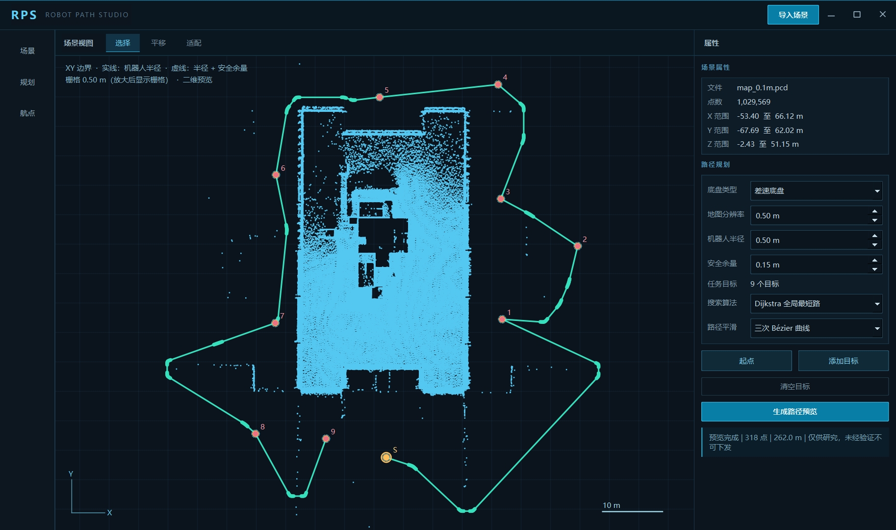
Plan on point clouds or 3D models
Set points and routes on the mapped site, using the same coordinate reference as the field rather than aligning by experience.
02
Automatic paths to target points
Generate a reachable path to a specified target, reducing manual point placement.
03
Paths through manual waypoints
Add manual waypoints and regenerate sections that need adjustment, balancing efficiency with operator control.
04
Route collision checks
Check interference with equipment, tunnel walls and doorframes during planning, before field execution.
Validate and deliver: from route to file
01
Simulation without hardware
Check route reachability, actions and timing without waiting for physical equipment.
02
Export mission files
Save routes, points, actions and parameters in a mission file for INES execution, separating planning from operations.
Plan once and repeat on compatible devices sharing the same coordinate reference. ARP already provides route planning and task output for bridges and confined spaces; this solution configures routes and missions for ground platforms.
Three payload types, chosen by what needs inspection
Choose payloads to match the inspection target, not simply the highest specification. Readings, temperatures and scene coverage call for different modules.
Three payload types, chosen by what needs inspection
Inspection target
Payload choice
Typical tasks
Readings, crack widths and corrosion areas
High-resolution imaging
Meter reading, deterioration checks and label verification
Temperature distribution, hot spots and leakage traces
Thermal imager
Overheating, leaks, fire risks and insulation failures
Wide-area video and adjustable-view review
Gimbal
Route video, intrusion checks, point review and observation before takeover
01
Gimbal
Adjust the view forward and sideways with presets at inspection points. Useful for tilt changes and surrounding observation; detailed interpretation still relies on high-resolution imaging and adequate stability.
02
High-resolution imaging
High-resolution visible-light capture with lighting and focus control supports readings and fine defects. Accuracy depends on distance, angle and illumination, so point poses should be fixed during planning.
03
Thermal imager
Records temperature distribution to identify hot spots and differences. Suitable for thermal and leakage-related anomalies; emissivity, distance and ambient temperature affect results, and absolute temperature needs onsite calibration.
Keep acquisition conditions consistent with one primary payload per mission. For multiple payloads, coordinate poses, exposure and temperature settings per project to preserve comparability.
06 · ANALYTICS
One inspection platform, three aligned data types
Visible-light images show appearance, thermal images show temperature, and point clouds locate the same anomaly. Aligning them provides context for interpretation.
01 / Visible light · Thermal · LiDAR
Intrusion analysis
Detect entry into configured zones and record time, location and images. Duty staff determine whether it constitutes an incident under site procedures.
02 / Visible light
Meter reading
Read meters at defined points and retain values and original images in daily or monthly sequences. Low-confidence entries are listed for manual review.
03 / Visible light · Thermal
Anomaly analysis
Compare visible and thermal results at the same location to distinguish temperature-only anomalies from visible changes accompanied by heating, reducing reliance on one data source.
04 / Visible light · Thermal
Structural deterioration
Archive crack, corrosion and seepage images by point for historical comparison of extent and appearance. Qualified staff assess defect grades under maintenance procedures.
Captured data upload to the platform and are filed by category. Resumable upload and offline buffering are project options. Analysis and evidence records do not replace professional inspection conclusions or field decisions.
Deployment depends on traversable ground, reliable positioning and a workable data-transfer plan. Resolve these prerequisites before deployment.
Applicable environments
01
Utility tunnels
Follow pipes, valves, joints and access points to reduce long walking entries; check leakage, insulation, valve status and standing water.
02
Operational and construction tunnels
Inspect beside tracks and along inverts, lower walls and cable trenches for cracks, seepage, spalling and clearance intrusions.
03
Equipment and electrical rooms
Read meters and temperatures at set points and inspect cabinets and cables for hot spots and deterioration.
04
Outdoor yards
Route-based checks of substations, tank areas and facility perimeters combine coverage with point review for intrusion, leaks, corrosion and visible equipment changes.
05
Mixed indoor–outdoor routes
One route enters a building or tunnel and returns outdoors, crossing RTK and GNSS-denied areas, such as yard-to-workshop or portal-to-tunnel tasks.
Deployment requirements
Deployment requirements
Deployment requirements
Requirements and notes
Ground traversability
Confirm slopes, steps, obstacles and protection ratings for the platform. Adjust routes or use stationary deployment where limits are exceeded.
Communications
Confirm relays, offline missions and transfer methods onsite. Files can be preloaded; disconnected execution and post-exit transfer must be validated per project.
Positioning reference
Confirm map accuracy and point marking before deployment, then reuse the same coordinate reference.
Payload calibration
Fix distance, angle and illumination during planning. Reassess historical comparisons if calibration conditions change.
Capability Boundary
01
Not a substitute for aerial or waterside work
Use suitable drones or other methods for bridge undersides, turbine blades and waterside areas inaccessible to ground platforms.
02
Long, repetitive or feature-poor passages
Laser SLAM may degrade in repetitive geometry; use markers, ground texture or intervention points as appropriate.
03
Water and special environments
Water depth, hazardous gases, dust and explosion protection need platform-specific confirmation; suitability is not assumed.
04
Payload accuracy is conditional
Thermal absolute temperatures and remote readings depend on distance, emissivity and lighting; performance is confirmed and accepted per project.
05
Endurance and mission duration
Coverage per mission depends on endurance, payload power and route length, calculated for the actual configuration.
Capabilities describe the solution; actual performance depends on ground conditions, communications, payloads and planning, subject to project validation and acceptance.
Quadruped inspection questions
How does it localise without satellite reception?
INES combines laser SLAM, vision and the IMU in GNSS-denied areas. Maps, scene features and switching strategies must be validated onsite.
Can slippery ground cause drift?
LiDAR, vision and IMU fusion helps estimate body position and attitude and reduces the effects of foot slip on positioning and route tracking, but does not eliminate ground risks. Assess water, oil, slopes and platform capability before deployment.
How long can a route be reused?
Reuse is possible while maps, coordinate references, equipment and points remain valid. Recheck and validate routes after layout, obstacle or calibration changes.
Does it replace human inspection?
It complements repeated close-to-ground capture, not professional defect grading, field risk assessment or operational decisions, nor aerial coverage by drones.
Drones, people and fixed sensors each have a role. Quadrupeds complement them with repeatable close-to-ground capture rather than replacing every method.
Choose the right inspection platform
Dimension
Rail inspection (TIDS / CIDS / SIDS)
Aerial inspection (BRIDGE / WIND / INDOOR)
Ground inspection (quadruped)
Coverage
Ahead of trains, carriages and stations
Bridge undersides, turbine blades and upper enclosed spaces
Utility tunnels, lower tunnel areas, equipment rooms and perimeters
Viewpoint
Onboard forward views and fixed points
Downward and side views at height
Ground-level horizontal and upward close views
Typical frequency
Continuous with operations
Scheduled sorties
Daily or per shift using mission files
Key constraints
Integration with existing systems
Airspace, airflow and endurance
Traversability, communications and positioning reference
Please share the site type and route length, inspection points (readings, temperature or images), communications, slopes, steps and water, any explosion-proof or special protection requirements, and existing platforms and data formats.